


Quick Research
Generate reliable direction feasibility study reports for your R&D in just a few steps.

Technical Q&A
Discover and master advanced knowledge NOW. Basics, ideas, possibilities, all at once.

Find Solutions
As an expert in R&D theories, this can generate solutions to your technical problems instantly.

Evaluate Feasibility
Analyze your overall solution with one click, know your potential R&D risks in advance.

Monitor Landscape
Get weekly tech updates, stay abreast of the latest tech innovations and key insights.
End mill and rotating shaft beam airfoil hyperboloid milling method based on end mill
An end mill and hyperboloid technology, applied in milling cutters, milling machine equipment, details of milling machine equipment, etc., can solve problems such as the inability to meet the needs of the machining of the hyperboloid surface of the aircraft shaft beam wing surface, the inability to geometrically mesh, and the difficult-to-cut materials.
- Summary
- Abstract
- Description
- Claims
- Application Information
AI Technical Summary
Problems solved by technology
Method used
Image


Examples
Embodiment 1
[0051] A kind of end milling cutter, comprises cutter bar and the end edge that is arranged on one end of cutter bar, such as Figure 4-Figure 8 As shown, the end edge is a concave structure, the end edge is provided with several cutting edges, and is provided with several helical side edges along the peripheral side, and the cutting edge includes a bottom edge in a concave arc structure, The gap between the bottom edge and the rotation plane of the bottom edge is H, and the two ends of the bottom edge are respectively connected to the helical side edge through arc segments.
[0052] Further, the end edge is provided with 14 cutting edges, and the end edge of the end mill 4 is provided with more cutting edges, so as to further improve the processing efficiency with the same feed rate per tooth.
[0053] Further, the bottom edge width B of the cutting edge is 0.6 mm to 0.8 mm, and H is 0.5 mm.
[0054] Further, the rake angle β of the end edge is 10°-12°, the relief angle γ of...
Embodiment 2
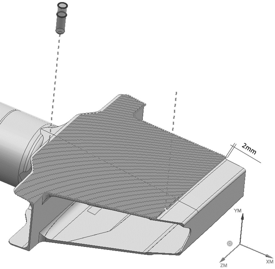
[0059] The milling method of the hyperboloid surface of the shaft beam airfoil based on the end mill 4 comprises the following steps:
[0060] Step S100: if image 3 As shown, the shaft beam part 3 is fixed on the workbench 1, so that the shaft beam wing surface is completely exposed and is in a machinable state;
[0061] Step S200: Roughly machining the airfoil of the rotating shaft beam, using an indexable milling cutter to perform rapid rough milling with a large margin, and roughly machining the airfoil of the rotating shaft beam into a trapezoidal small step surface;
[0062] Step S300: semi-finishing the airfoil of the shaft beam, using the end mill 4 to reciprocate the tool with a variable swing angle to semi-finish the surface with a large line spacing;
[0063] Step S400: finish machining the airfoil of the shaft beam, using an end mill with 4 large strokes to finish milling the profile in place.
[0064] In the present invention, the large-diameter fast-feed indexa...
Embodiment 3
[0066] This embodiment is optimized on the basis of Embodiment 2. In the step S200, when the indexable milling cutter has a large margin for rough milling, the depth of cut ap=0.8mm, the width of cut ae=65%D, and the linear speed Vc= 45m / min, feed per tooth fz=0.8mm / z.
[0067] Further, the indexable milling cutter in the step S200 has a diameter D≥50 mm, a base angle R≥1 mm, and a number of teeth Zn≥5.
[0068] Other parts of this embodiment are the same as those of Embodiment 2 above, so details are not repeated here.
PUM
 Abstract
Description
Claims
Application Information
 - R&D Engineer
- R&D Manager
- IP Professional
- Industry Leading Data Capabilities
- Powerful AI technology
- Patent DNA Extraction
Browse by: Latest US Patents, China's latest patents, Technical Efficacy Thesaurus, Application Domain, Technology Topic, Popular Technical Reports.
© 2024 PatSnap. All rights reserved.Legal|Privacy policy|Modern Slavery Act Transparency Statement|Sitemap|About US| Contact US: help@patsnap.com