
A Composite Dielectric Millimeter Wave Filter Based on Multilayer Technology

A composite medium and filter technology, applied in the field of filters, can solve problems such as mutual coupling and crosstalk of non-correlated resonant units, reduction of filter circuit Q value, and deterioration of out-of-band suppression, so as to reduce noise and clutter interference, Low insertion loss and physical size reduction effect

Active Publication Date: 2022-03-01
UNIV OF ELECTRONICS SCI & TECH OF CHINA
View PDF6 Cites 0 Cited by
  • Summary
  • Abstract
  • Description
  • Claims
  • Application Information

AI Technical Summary

Problems solved by technology

[0004] However, integrating multiple millimeter-wave resonant units in a very compact volume space to achieve good selection characteristics of LTCC filters can easily cause mutual coupling and crosstalk between non-correlated resonant units, resulting in unnecessary spurious passbands , causing the Q value of the filter circuit to decrease, the insertion loss to increase, and the out-of-band rejection to deteriorate

Method used


Image

  • A Composite Dielectric Millimeter Wave Filter Based on Multilayer Technology
  • A Composite Dielectric Millimeter Wave Filter Based on Multilayer Technology
  • A Composite Dielectric Millimeter Wave Filter Based on Multilayer Technology

Examples


Embodiment Construction

[0032] The specific embodiments of the present invention are described below so that those skilled in the art can understand the present invention, but it should be clear that the present invention is not limited to the scope of the specific embodiments. For those of ordinary skill in the art, as long as various changes Within the spirit and scope of the present invention defined and determined by the appended claims, these changes are obvious, and all inventions and creations using the concept of the present invention are included in the protection list.

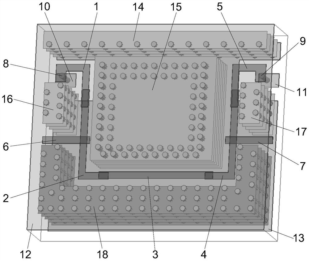
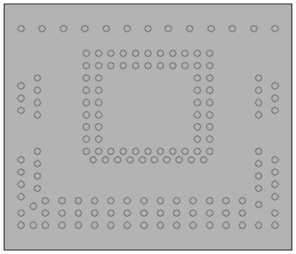
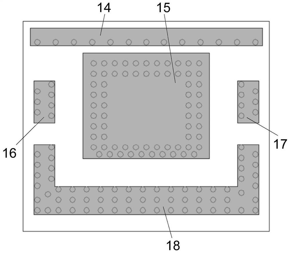
[0033] Such as Figure 1 to Figure 8 A composite dielectric millimeter-wave filter shown in , which includes a composite dielectric body, a main circuit layer disposed in the composite dielectric body, an interference isolation wall, and an external electrode disposed at the bottom of the dielectric body.

[0034] In this solution, the multilayer circuit of the filter can be built into the ceramic dielectric body based on t...


PUM

PropertyMeasurementUnit
dielectric lossaaaaaaaaaa

Abstract

The invention discloses a millimeter-wave band-pass filter of a composite medium, which has a multi-layer circuit structure. By setting up interference isolation walls around the main circuit and using corresponding dielectric materials in different circuit layer areas, the good frequency selection characteristics of the millimeter wave filter can be realized in a very small package volume, and the advantage of using no dielectric material Features minimize mutual coupling between unrelated resonant elements and reduce the effects of parasitic parameters. The composite dielectric millimeter wave filter proposed by the present invention can realize a stop-band suppression up to 30dB when the maximum insertion loss is only 1.2dB, and has the characteristics of miniaturization, low insertion loss and high isolation. The millimeter-wave bandpass filter includes a composite dielectric body, a main circuit layer, an interference isolation wall, and an external electrode at the bottom of the dielectric body. The external electrodes are respectively input ports, output ports, and ground ports, and the ground ports include a top-layer ground port and a bottom layer. ground port.

Description

technical field [0001] The invention relates to filters, in particular to a composite dielectric millimeter wave filter based on multilayer technology. Background technique [0002] With the rapid development of the fifth-generation mobile communication technology, mobile data traffic has increased sharply, and it can no longer rely on the evolution of various low-frequency wireless transmission and networking technologies, and more wireless spectrum resources need to be adopted. Millimeter wave technology can realize ultra-high-speed wireless data transmission by increasing the spectrum bandwidth, thus becoming one of the keys in 5G communication technology. As a key device in the communication system, the filter plays an important role in frequency selection, and its performance has a crucial impact on the transmission quality of the communication system. In broadband and ultra-wideband channelized transceiver components, filters are an essential part, and their performan...

Claims


Application Information

Patent Timeline
Patent Type & Authority Patents(China)
IPC IPC(8): H01P1/20
CPCH01P1/2002
Inventor 钱可伟陈香茹田忠
Owner UNIV OF ELECTRONICS SCI & TECH OF CHINA
Learn More