Efficient steel wire rope winding machine

A rope-receiving machine and steel wire rope technology, which is applied in the direction of conveying filamentous materials, thin material processing, transportation and packaging, etc., can solve the problems of loose wire rope of the rope-receiving wheel, low rope-receiving efficiency, complex structure, etc. The effect of weight, ensuring stability, and simple structure

Pending Publication Date: 2021-08-27
河南富控电梯有限公司
View PDF0 Cites 0 Cited by
  • Summary
  • Abstract
  • Description
  • Claims
  • Application Information

AI Technical Summary

Problems solved by technology

[0002] The steel wire rope is mainly used for lifting, hanging and pulling operations during the construction process. After the steel wire rope is used up, the steel wire rope needs to be taken up and wound on the rope take-up wheel, and then the steel wire rope should be stored. At present, the rope take-up operation is usually done manually by workers. When the wire rope is wound on the rope take-up wheel, when the wire rope is too long, it needs multiple people to work together, which is time-consuming and labor-intensive. Not only can the uniformity of the rope take-up be not guaranteed, but also the wire rope on the rope take-up wheel will become loose, which will affect the next use.
At present, there are also automatic rope-receiving devices on the market, but they have the disadvantages of complex structure and heavy weight. Especially after a steel wire rope has been collected, the rope-retracting wheel that is wrapped around the wire rope needs to be removed from the frame of the automatic rope-retracting device, and then installed. An empty rope take-up wheel is used for the rope take-up operation of the next steel wire rope. The operation process of switching the rope take-up wheel takes a long time, resulting in a low overall rope take-up efficiency

Method used


Image

  • Efficient steel wire rope winding machine
  • Efficient steel wire rope winding machine
  • Efficient steel wire rope winding machine

Examples


Embodiment Construction

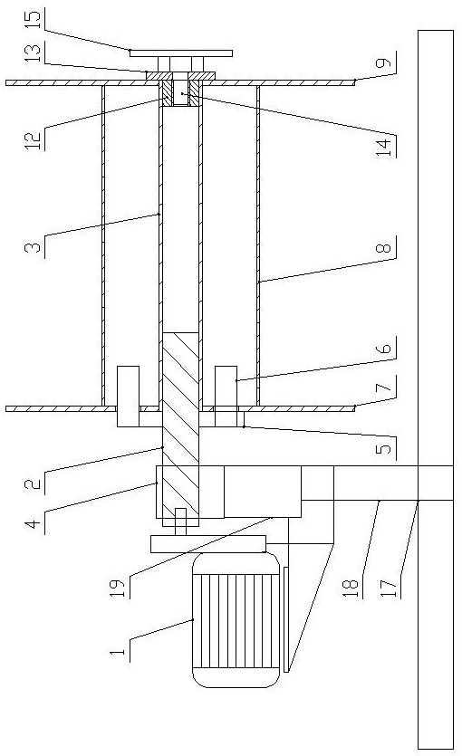
[0022] like Figure 1-Figure 6 As shown, the wire rope high-efficiency rope receiving machine of the present invention comprises a frame and a motor speed reducer 1 arranged on the frame. It is connected to the left end of the drive shaft by transmission. The outer circle of the drive shaft is coaxially equipped with a rope take-up wheel. The left side of the outer circle of the drive shaft is detachably connected to the left end of the rope take-up wheel through the drive disc claw assembly. The right end of the drive shaft is provided with an axial An easy-to-disassemble positioning assembly for positioning the rope take-up pulley.

[0023] Drive shaft comprises connection shaft 2 and drive pipe 3, and connection shaft 2 right ends stretches into and is fixed in the left port of drive pipe 3, and frame is provided with bearing seat 4, and connection shaft 2 is connected on the bearing seat 4 by bearing assembly rotation.

[0024] The drive disc claw assembly includes a driv...


PUM


Abstract

An efficient steel wire rope winding machine comprises a machine frame and a motor speed reducer arranged on the machine frame, a driving shaft horizontally arranged in the left-right direction is rotationally arranged on the machine frame, a power output shaft of the motor speed reducer is in transmission connection with the left end of the driving shaft, and a rope winding wheel is coaxially arranged on the outer circle of the driving shaft; and the left side of the outer circle of the driving shaft is in detachable transmission connection with the left end of the rope winding wheel through a driving disc claw assembly, and the right end of the driving shaft is provided with an easy-to-disassemble-and-assemble positioning assembly used for axially positioning the rope winding wheel. The efficient steel wire rope winding machine is simple in structure, easy to manufacture and light in weight, operation is convenient and fast when the rope winding wheel is replaced, multiple steel wire ropes can be wound in sequence, and the rope winding efficiency is greatly improved.

Description

technical field [0001] The invention belongs to the technical field of building construction, and in particular relates to a high-efficiency rope take-up machine for steel wire ropes. Background technique [0002] The steel wire rope is mainly used for lifting, hanging and pulling operations during the construction process. After the steel wire rope is used up, the steel wire rope needs to be taken up and wound on the rope take-up wheel, and then the steel wire rope should be stored. At present, the rope take-up operation is usually done manually by workers. When the wire rope is wound on the rope take-up wheel, when the wire rope is too long, it needs multiple people to work together, which is time-consuming and labor-intensive. Not only can the uniformity of the rope take-up be not guaranteed, but also the wire rope on the rope take-up wheel will become loose, which will affect the next use. . At present, there are also automatic rope-receiving devices on the market, but ...

Claims


Application Information

Patent Timeline
Patent Type & Authority Applications(China)
IPC IPC(8): B65H67/04B65H54/70B65H54/547B65H54/44B65H79/00
CPCB65H54/70B65H54/547B65H54/44B65H67/0411B65H67/0417B65H79/00B65H2701/35B65H2701/173
Inventor 谢利明赵鑫李殿柱陈莹
Owner 河南富控电梯有限公司
Why Eureka
Try Eureka