Rolling method for wide metal strap foil

A metal strip and wide-width technology, applied in the directions of metal rolling, metal rolling, metal rolling stands, etc., can solve the problems of low rigidity, unsuitable for thinning, restricting high-precision wide-width strip and foil rolling, etc. Curl deformation problem, effect in favor of thinning, significant application value and economic value

Active Publication Date: 2021-08-24
SHANGHAI WUXING COPPER CO LTD +1
View PDF6 Cites 1 Cited by
  • Summary
  • Abstract
  • Description
  • Claims
  • Application Information

AI Technical Summary

Problems solved by technology

It is well known that the smaller the diameter of the work roll, the more favorable it is for the thinning of the strip foil 5, but it also brings problems: in Figure 4 Among them, the diameter of the left working roll is small, the rigidity is small, the bite angle of the strip foil 5 is large, and the lateral component of the rolling force is large, so its lateral bending tendency is large
[0008] To sum up, small-diameter work rolls are good for thinning, but limited by the difficulty in controlling the rolled strip shape, so the rolling width should not be too large; while large-diameter work rolls are conducive to the control of rolled strip shape and are suitable for rolling. Wide, but not suitable for rolling thin
For wide strip foil with a thickness of less than 0.3mm, the diameter of the work roll must be small enough (usually 25-50mm in diameter) to obtain a large amount of rolling reduction, and the shape of the plate at this time will be very difficult to control , which is currently the bottleneck restricting high-precision wide-width strip and foil rolling

Method used


Image

  • Rolling method for wide metal strap foil
  • Rolling method for wide metal strap foil
  • Rolling method for wide metal strap foil

Examples


Embodiment 1

[0053] The invention discloses a rolling method of wide-width metal strip and foil, which is used for rolling copper alloy strip and foil. The final rolling thickness of the copper alloy strip and foil is 0.01mm, and the width is 800mm. The boundary thickness of the strip and the foil is 0.15mm, and the thickness of the copper alloy strip and foil (hereinafter referred to as the strip foil) already belongs to the foil. Due to the high deformation resistance of copper alloy, it is difficult to ensure the flatness of its plate shape.

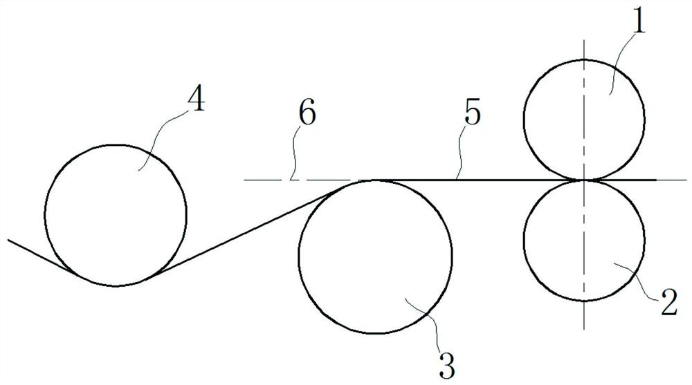
[0054] Such as Figure 5 As shown, a flattening roller 3 is arranged on the entrance side of the roll gap, and the roll surface of the flattening roller 3 is lower than the rolling centerline 6. After the strip foil 5 passes through the front stretching of the flattening roller 3, it enters obliquely upwards and is formed by a pair of working rollers. In the roll gap formed by the rolls, the roll diameter of the upper work roll 1 is 30 mm, the ro...

Embodiment 2

[0069] Such as Figure 12 As shown, the difference between this embodiment and Embodiment 1 is that the strip foil 5 enters the roll gap horizontally along the rolling centerline 6, and a flattening roll 3 is arranged on the exit side of the roll gap, and the roll surface of the flattening roll 3 is as high as On the rolling centerline 6. The flattening roller 3 post-stretches the strip foil 5 so that the strip foil 5 forms an exit-side cladding arc on the roll surface of the upper working roll 1, and the cladding angle of the exit-side cladding arc is β, and β is also 30°. Due to the existence of the wrapping arc on the exit side, the upper work roll 1 backs up the strip foil 5, and the tension is evenly distributed on the cross section of the wrapping arc on the exit side. The principle is as follows:

[0070] Such as Figure 13 As shown, the strip foil 5 flowing out from the roll gap is wrapped on the upper work roll 1 to form an outlet-side wrapping arc. Since the linea...

Embodiment 3

[0075] This embodiment can be regarded as a combination of Embodiment 1 and Embodiment 2, such as Figure 14 As shown, the strip foil 5 forms an entry-side cladding arc with the lower work roll 2 on the entrance side of the roll gap, and the cladding angle α of the entrance-side cladding arc is 30°; the strip foil 5 works on the exit side and the upper work roll of the roll gap The roll 1 forms an exit-side cladding arc, and the cladding angle β of the exit-side cladding arc is also 30°. Due to the existence of the entrance-side cladding arc and the exit-side cladding arc, the lower work roll 2 and the upper work roll 1 respectively produce back support for the strip foil 5 .

[0076] The function and influence of the cladding arc on the entrance side in rolling has been explained in Example 1, and the function and influence of the cladding arc on the exit side in rolling has been explained in Example 2, so it will not be repeated here. It is worth noting that if Figure 13 ...


PUM


Abstract

The invention relates to a rolling method for a wide metal strap foil. By using a rolling mill with unequal working rollers, the roller diameter of one working roller of the rolling mill is greater than that of another working roller. During rolling, the linear speeds of roll surfaces of two working rollers are same, and the metal strap foil is wrapped to the roll surface of one working roller at an inlet side or an outlet side of a roller gap formed by the two working rollers to form a wrapping arc. Backed up by the working roller, tension of the metal strap foil is uniformly distributed on cross section of the wrapping arc. The strap foil is rolled by using the rolling mill with unequal working rollers, so that it is favorable to thin the strap foil and obtain a better plate shape. In addition, the wrapping arc is formed on the working roller of the strap foil, and backed up by the working roller, the front tension of the strap foil is uniformly distributed on the cross section of the wrapping arc at the inlet side, so that uniform tension rolling of the strap foil is realized, a bottleneck that restrains development of the strap foil in wider, thinner and more ideal plate shape is broken through, and the technical problem in the industry is solved.

Description

technical field [0001] The invention relates to the technical field of rolling, in particular to a rolling method of high-precision wide-width metal strips and foils, which is used to obtain good plate shapes. Background technique [0002] With the advancement of the technology industry, the market demand for high-precision wide-width thin strips and foils (hereinafter referred to as strips and foils) is becoming more and more urgent. Under the current technical background, the rolling technology for wide and thick strips is basically mature, but the technical bottleneck has emerged in the rolling technology of high-precision wide and thinner strips and foils, and a breakthrough is urgently needed. For thicker strips, even if there are shape defects after rolling, the shape can still be corrected by tension leveling or other leveling means, while for thinner strips and foils, especially very thin foils, due to lack of follow-up The shape correction means, the original rolli...

Claims


Application Information

Patent Timeline
IPC IPC(8): B21B1/40
CPCB21B1/40B21B39/16B21B37/68B21B37/48B21B27/021B21B37/46B21B13/023
Inventor 刘洪勤马力徐继玲李毅
Owner SHANGHAI WUXING COPPER CO LTD
Why Eureka
Try Eureka