Method for preparing laser cladding layer of cutting edge of cutter based on powder-cored wire deep penetration mode

A laser cladding, powder core wire technology, applied in coating, metal material coating process and other directions, can solve the problem of low deposition efficiency, achieve the effect of excellent performance, increase melting efficiency, and reduce melting amount

Active Publication Date: 2021-08-20
BEIJING UNIV OF TECH
View PDF6 Cites 0 Cited by
  • Summary
  • Abstract
  • Description
  • Claims
  • Application Information

AI Technical Summary

Problems solved by technology

[0004] The laser cladding process is a relatively advanced manufacturing technology that can be used to prepare coatings on the cutting edge of the tool, but its deposition efficiency is low

Method used


Image

  • Method for preparing laser cladding layer of cutting edge of cutter based on powder-cored wire deep penetration mode
  • Method for preparing laser cladding layer of cutting edge of cutter based on powder-cored wire deep penetration mode
  • Method for preparing laser cladding layer of cutting edge of cutter based on powder-cored wire deep penetration mode

Examples


Embodiment 1

[0037] This embodiment provides a method for preparing a laser cladding layer on a cutting edge based on a powder core wire material deep fusion mode, including:

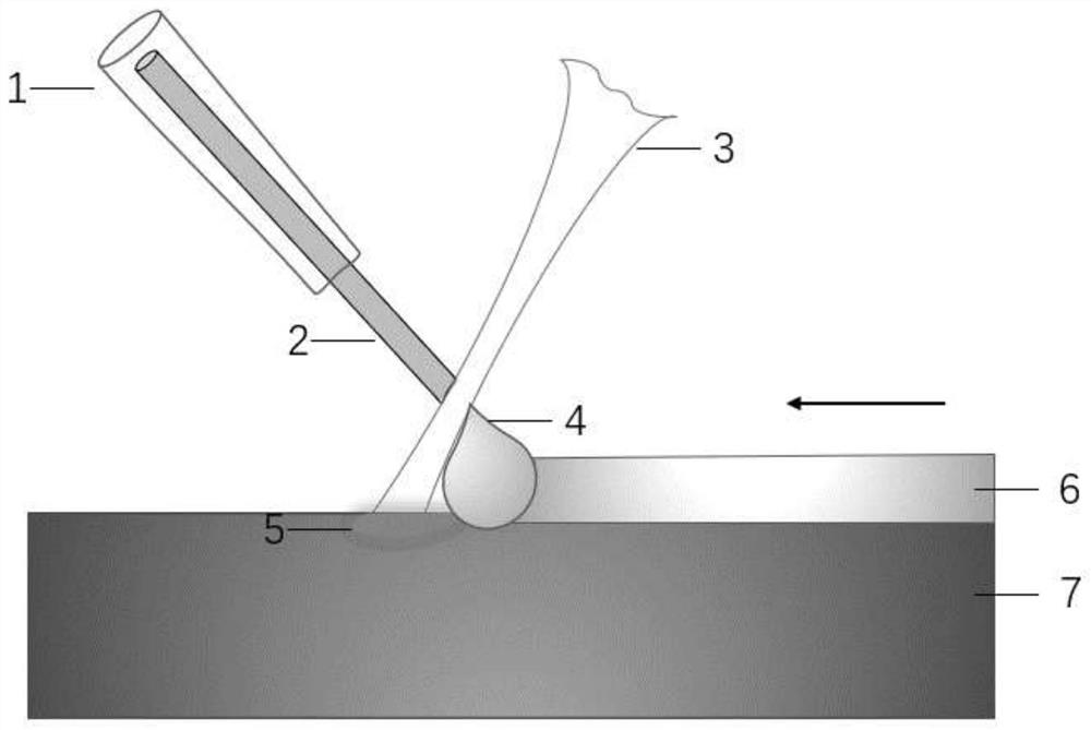
[0038] The powder-cored welding wire and the laser beam are arranged on both sides of the normal line of the cutting edge plane at a certain angle.

[0039] The shielding gas is loaded coaxially with the powder cored wire, and the flow direction of the shielding gas is consistent with the feeding direction of the powder cored wire.

[0040] The laser beam is directly applied to the surface of the powder-cored welding wire in a certain defocused state, and the position of the spot is separated from the cutting edge substrate by a certain distance, so that the powder-cored welding wire melts in a deep melting mode and transitions to the cutting edge substrate below surface, forming a cladding layer.

[0041] In a preferred embodiment, the laser spot diameter of the laser beam acting on the surface of the powder cored...

Embodiment 2

[0054] This embodiment provides a tool edge laser cladding system, including:

[0055] A wire feeding device capable of feeding powder-cored welding wire to the cutting edge of the tool;

[0056] A laser output device, which is set so that the powder cored wire and the laser beam are arranged at a certain angle on both sides of the normal line of the cutting edge plane;

[0057] The wire feeding device is a coaxial shielded wire feeding device, which is set so that the shielding gas is loaded coaxially with the powder cored wire, and the flow direction of the shielding gas is consistent with the feeding direction of the powder cored wire;

[0058] The laser beam of the laser output device directly acts on the surface of the powder-cored welding wire in a certain defocused state, and the position of the light spot is separated from the base material of the cutting edge by a certain distance, so that the powder-cored welding wire melts in a deep melting mode and transitions to t...


PUM


Abstract

The invention provides a method for preparing a laser cladding layer of a cutting edge of a cutter based on a powder-cored wire deep penetration mode, and a system for implementing the method. A powder-cored wire and a laser beam are arranged on the two sides of the normal of a cutting edge plane at a certain angle, the laser beam directly acts on the welding wire in a certain defocusing state, the acting position of a light spot and the surface of the cutting edge are spaced by a certain distance, and the welding wire is melted in a deep melting mode and transited to the cutting edge to form a cladding layer; the diameter of the light spot is slightly larger than the diameter of the welding wire, transmitted light beams are low in energy, and the two sides of the cutting edge are heated and melted in a heat conduction mode. According to the method, the forming efficiency of the powder-cored wire can be improved, and the melting efficiency of the welding wire and internal alloy powder can be greatly improved by melting the powder-cored wire in a deep melting mode; and the light beams penetrating through the two sides can play a good role in preheating the cutting edge base plate, so that the cladding quality is improved.

Description

technical field [0001] The invention relates to a method for preparing a laser cladding layer on a cutting edge of a tool based on a deep melting mode of a powder-cored welding wire, and belongs to the technical field of advanced laser manufacturing. Background technique [0002] Many domestic knives production companies still use the traditional knives production process. At the same time, the performance of domestic steel used to produce knives is lower than that of steel in other developed countries, which makes domestic knives difficult in terms of hardness and wear resistance. Meet people's needs in production and life. At present, many enterprises use high-quality steel imported from abroad as the raw material for the production of knives, such as Japanese laminated steel. Domestic enterprises can indeed produce high-quality knives by using this imported high-quality steel, but this kind of steel is expensive to import, which greatly increases the cost. Relying on th...

Claims


Application Information

Patent Timeline
IPC IPC(8): C23C24/10
CPCC23C24/103Y02P10/25
Inventor 黄婷郭鹏肖荣诗
Owner BEIJING UNIV OF TECH
Why Eureka
Try Eureka