Device for heating fuel oil by using exhaust gas of exhaust pipe

A technology of exhaust pipe and heat exchange device, which is applied in the direction of fuel heat treatment device, combustion air/combustion-air treatment, charging system, etc. It can solve the problems of high energy consumption, fuel overheating and explosion, and difficult layout, etc., to achieve optimization The effect of the combustion system

Pending Publication Date: 2021-08-10
SHANGHAI JIAO TONG UNIV
View PDF5 Cites 0 Cited by
  • Summary
  • Abstract
  • Description
  • Claims
  • Application Information

AI Technical Summary

Problems solved by technology

[0006] The electrical system of the current electric heating method is relatively complicated, and it is generally integrated on the cylinder body, making it difficult to arrange
In addition, the way of electric heating consumes more energy, and the benefits in terms of the thermal efficiency of the whole machine are reduced
In addition, there are dangers such as electric leakage, reduced reliability, overheating and explosion of fuel oil, etc.

Method used


Image

  • Device for heating fuel oil by using exhaust gas of exhaust pipe

Examples


Embodiment Construction

[0025] The following describes several preferred embodiments of the present invention with reference to the accompanying drawings, so as to make the technical content clearer and easier to understand. The present invention can be embodied in many different forms of embodiments, and the protection scope of the present invention is not limited to the embodiments mentioned herein.

[0026] In the drawings, components with the same structure are denoted by the same numerals, and components with similar structures or functions are denoted by similar numerals. The size and thickness of each component shown in the drawings are shown arbitrarily, and the present invention does not limit the size and thickness of each component. In order to make the illustration clearer, the thickness of parts is appropriately exaggerated in some places in the drawings.

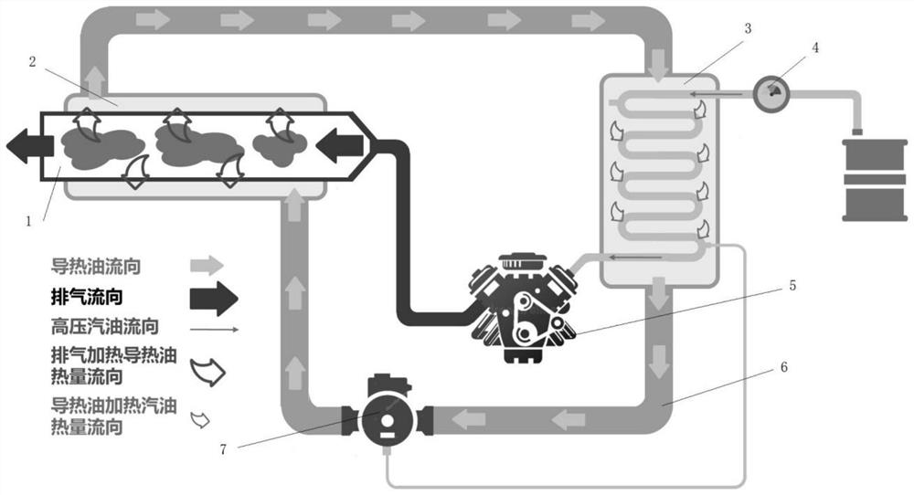
[0027] figure 1 A schematic diagram of the overall structure of a device for heating fuel oil using exhaust gas from an exhaust pi...


PUM


Abstract

The invention discloses a device for heating fuel oil by using exhaust gas of an exhaust pipe. The device is characterized by comprising a first heat exchange device, a second heat exchange device, a driving pump, a pipeline and a heat exchange medium, wherein the first heat exchange device, the second heat exchange device and the driving pump are connected through the pipeline to form a closed system; the heat exchange medium is placed in the closed system; the first heat exchange device is arranged outside the exhaust pipe of an engine; and the second heat exchange device is arranged outside a fuel oil pipe of the engine. According to the technical scheme provided by the invention, explosion-proof heating oil is used for recovering waste heat of the exhaust gas, the waste heat is recovered as much as possible for heating the fuel oil on the premise of not influencing aftertreatment such as three-way catalysis, and a combustion system is further optimized while the current highest energy conservation and emission reduction technology is met. The system is safe, reliable, energy-saving and environment-friendly, and the waste heat can be greatly recovered and effectively utilized.

Description

technical field [0001] The invention relates to the technical field of automobile fuel heating, in particular to a device for heating fuel by using exhaust gas from an exhaust pipe. Background technique [0002] In the design process of the core combustion system of the engine, fuel atomization is the core technology to achieve clean and efficient combustion. How to achieve high-efficiency fuel atomization to better mix fuel and air into a homogeneous gas is the key to energy saving and emission reduction of the combustion system . At present, the main technical method for fuel atomization is high-pressure injection, that is, to use the pressure difference between fuel and back pressure to carry out broken atomization by increasing the fuel rail pressure. [0003] After research, it is found that properly raising the fuel temperature and realizing fuel flash spray can significantly improve the fuel atomization and evaporation effects under low fuel injection pressure condit...

Claims


Application Information

Patent Timeline
IPC IPC(8): F02M31/16F02G5/02
CPCF02M31/16F02G5/02Y02T10/12
Inventor 许敏李雪松孙哲崔明利徐宏昌王鸿雨王森袁志远
Owner SHANGHAI JIAO TONG UNIV
Why Eureka
Try Eureka