
Controllable porous calcium phosphate scaffold and preparation method thereof

A porous calcium phosphate and calcium phosphate technology, applied in the field of bone repair medical materials, can solve the problems of changing the degradation rate of the stent, the single through-hole structure, and the low degree of control, achieve good cell compatibility, meet the requirements of bone repair, The effect of easy process flow

Pending Publication Date: 2021-08-10
SICHUAN UNIV
View PDF7 Cites 3 Cited by
  • Summary
  • Abstract
  • Description
  • Claims
  • Application Information

AI Technical Summary

Problems solved by technology

However, there are also disadvantages in the preparation of sacrificial molds by FDM. That is, because FDM uses nozzles to extrude molten materials, the printed structure is very limited, and the accuracy depends on the diameter of the nozzle. The diameter of the nozzle used in this patent is 0.3 mm, which cannot prepare fine structures. The through-pore structure is very single, and it may not be possible to prepare a pore-structured scaffold that is conducive to the growth of cells and tissues, which in turn affects the biological activity and osteoconductivity of the scaffold.
[0006] Therefore, a way of combining casting technology with 3D printing printing technology is designed, so that the scaffold has a microporous structure and through holes between micropores in the case of complex shapes and through macro holes; improved bone grafting The controllability of the pore structure in the stent is low, and the adjustable pore diameter range is small. Controlling the pore structure will change the degradation rate of the scaffold. At the same time, the pore structure will also affect the growth rate and volume of new bone and blood vessels. Bioactivity and osteogenicity of implanted scaffolds, it is necessary for those skilled in the art

Method used


Image

  • Controllable porous calcium phosphate scaffold and preparation method thereof
  • Controllable porous calcium phosphate scaffold and preparation method thereof
  • Controllable porous calcium phosphate scaffold and preparation method thereof

Examples


Embodiment 1

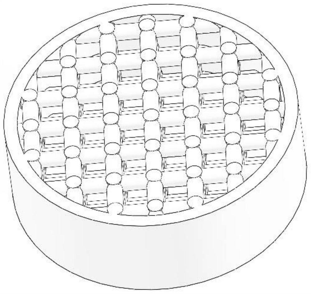
[0054] figure 1 It is a software modeling diagram of the calcium phosphate stent, and the shape of the calcium phosphate stent is matched and designed according to the defect site of the patient.

[0055] as attached figure 2 As shown, a controllable porous calcium phosphate scaffold, the composition of the calcium phosphate scaffold includes calcium phosphorus ceramics and calcium phosphate bone cement, the calcium phosphate scaffold is provided with a pore structure, the pore structure includes a macroporous structure, a microporous structure A pore structure and a through-hole structure, the calcium phosphate scaffold has a crystal structure, and a through-hole structure is arranged between the crystal structures.

[0056] Further, the calcium phosphorus ceramics include one or more combinations of hydroxyapatite and tricalcium phosphate.

[0057] Further, the calcium phosphate bone cement includes tetracalcium phosphate, octacalcium phosphate, calcium dihydrogen phospha...

Embodiment 2

[0072] This embodiment is carried out on the basis of the above-mentioned embodiment 1, and the similarities with the above-mentioned embodiment 1 will not be repeated.

[0073] This embodiment mainly introduces the regulation method of the pore structure of the scaffold.

[0074] The method for adjusting the aperture of the macroporous structure includes adjusting model precision and 3D printer precision; the source of the macroporous structure is that the sacrificial mold prepared by the printer is obtained after demoulding, so the size and shape of the macroporous structure depend on The size and shape of the printed sacrificial mold, and the minimum size of the sacrificial mold depend on the accuracy of the printer, so the size and shape of the macro-pore structure is prepared by building a model with software and demoulding after 3D printing.

[0075] The method for adjusting the pore diameter of the microporous structure includes adjusting the size and shape of the pore-...

Embodiment 3

[0080] This embodiment is carried out on the basis of the above-mentioned embodiment 1, and the similarities with the above-mentioned embodiment 1 will not be repeated.

[0081] This embodiment mainly introduces a preparation method of a scaffold with 60% porosity, 400 μm penetrating macropores, 60 μm spherical micropores, and appropriate amount of intercrystalline through holes.

[0082] Photosensitive resin is used as the sacrificial mold material for the bracket, 60 μm PMMA microspheres are used as the pore-forming agent, and the pouring slurry is a mixture of hydroxyapatite and α-tricalcium phosphate.

[0083] Implementation steps include:

[0084] S301. Prefabricate photosensitive resin sacrificial model with SLA 3D printer: first use solidworks software to construct a cylinder model with a diameter of 10mm and a height of 3mm, and build an interconnected cylinder structure in this model, with a diameter of 400μm, and form a 400μm after demoulding The through-macro holes...


PUM

PropertyMeasurementUnit
pore sizeaaaaaaaaaa
pore sizeaaaaaaaaaa
diameteraaaaaaaaaa

Abstract

The invention relates to a controllable porous calcium phosphate scaffold and a preparation method thereof. The calcium phosphate scaffold comprises calcium phosphate ceramic and calcium phosphate bone cement, the calcium phosphate scaffold is provided with a pore structure, the pore structure comprises a macro-pore structure, a micro-pore structure and a through-pore structure, and the calcium phosphate scaffold comprises crystal structures; and a through hole structure is arranged between the crystal structures, and the shape of the calcium phosphate stent is matched and designed according to the defect part of a patient. The preparation method of the sacrificial material is improved, a 3D printing technology with higher precision is selected, and more complex and diversified pore structures can be prepared; the prepared stent is provided with controllable micropores and through holes among crystals of the stent, the degradation rate of the stent is changed by controlling the pore structure, meanwhile, the ingrowth rate and ingrowth volume of new bones and blood vessels are affected by the pore structure, and therefore the biological activity and osteogenesis of the bone implantation stent are further improved; and the technological process is simple and easy to operate, and the prepared scaffold is stable in structural performance, high in compressive strength and good in cell compatibility.

Description

technical field [0001] The invention relates to the field of bone repair medical materials, in particular to a controllable porous calcium phosphate scaffold and a preparation method thereof. Background technique [0002] For orthopedic surgeons, the repair of large segmental bone defects caused by trauma, tumors, infections and congenital malformations is still a challenge. Such irregular bone defects require filling materials with good shape adaptability to fill the defect. . In recent years, with the continuous development of 3D printing technology, it is not difficult to prepare such scaffolds that require complex shapes and structures, but it is still difficult to prepare scaffolds that meet the conditions of bone repair in all aspects. [0003] At present, 3D printing is mostly direct printing, that is, the printing structure is equal to the final model, and the printing materials and printing methods need to be properly adapted, which means that various 3D printing m...

Claims


Application Information

Patent Timeline
Patent Type & Authority Applications(China)
IPC IPC(8): C04B35/447C04B38/06C04B38/04A61L27/10A61L27/12A61L27/50A61L27/56C04B28/34
CPCC04B35/447C04B38/067C04B38/04A61L27/12A61L27/10A61L27/56A61L27/50C04B28/344A61L2430/02C04B2235/96C04B38/0074C04B38/0054
Inventor 郭立坤贾恒星朱向东樊渝江张兴栋
Owner SICHUAN UNIV
Learn More