
Composite bulletproof plate and coating method

A ballistic plate and cladding technology, applied in chemical instruments and methods, protective clothing, protective equipment, etc., can solve the problems of complex molding process, low production efficiency, large back plate, etc., to reduce process steps, improve production efficiency, The effect of simple molding process

Active Publication Date: 2021-08-03
中航装甲科技有限公司
View PDF7 Cites 1 Cited by
  • Summary
  • Abstract
  • Description
  • Claims
  • Application Information

AI Technical Summary

Problems solved by technology

[0003]At present, through the development and innovation of technology, the ceramic composite bulletproof plate is generally prepared by bonding and compounding the crack arrest layer, the ceramic layer and the back plate composite material layer. The anti-crack layer is mainly used to cover the outer surface of the ceramic layer to avoid secondary damage caused by the splash of fragments generated by the ceramic sheet when it is subjected to impact resistance. At present, the coating of the anti-crack layer is generally to cut high-performance fiber two-dimensional woven fabric into pieces After brushing glue or laying an adhesive film on the surface of the composite material of the ceramic plate and the back plate, and then aligning and placing the anti-crack layer, ceramic layer, adhesive film and the composite material of the back plate in sequence, it is formed by manual laying and pressing, so that not only The production efficiency is low; and the uneven laying force of the anti-crack fabric will cause uneven thickness of the coating glue or dislocation of the glue film, resulting in uneven surface of the ballistic plate product, which will affect the product quality
In addition, the two-dimensional anti-crack fabric used in the existing technology can only protect the outer surface of the ceramic from the impact of the fragments from causing secondary damage, while the fragments on the side of the ceramic cannot be protected. At the same time, the ceramic plate and the The interlayer performance of the composite material backboard is poor, and the bulletproof performance of the bulletproof board will decrease or the backboard will have a large back convex due to layering when it is impacted by bullets
The patent application with the publication number 110953933A discloses a three-dimensional constrained ceramic composite bulletproof panel. The tubular fabric on the surface of the bulletproof panel is orthogonally nested to form a boxed cladding layer, thereby realizing three-dimensional constraint. In the ceramic composite panel The ceramic layer and the fiber-reinforced composite material plate are bonded by adhesive film or adhesive, and the one-time covering of tubular fabric and adhesive film cannot be realized.
In addition, due to the high toughness and low melting point of PE composite materials, in order to achieve effective protection against armor-piercing incendiary bombs and give full play to the protection capabilities of ceramics and composite materials, high-strength, high-strength mold and high-temperature-resistant transition layer composite materials; the patent application publication number 112484575A discloses a bullet-proof insert with a fiber slow-release layer, which introduces a carbon fiber plate between the ceramic bullet-resisting layer and the fiber slow-release layer, It effectively improves its defense performance against heavy machine gun armor-piercing incendiary bombs, but its molding process is complicated and the efficiency is low

Method used

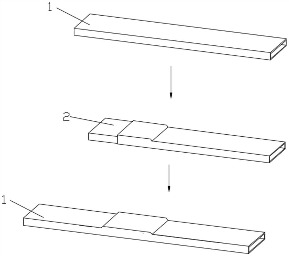

Image

  • Composite bulletproof plate and coating method
  • Composite bulletproof plate and coating method
  • Composite bulletproof plate and coating method

Examples


Embodiment 1

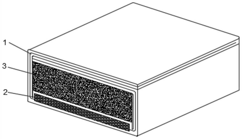
[0035] A composite bulletproof plate, such as figure 2 As shown, it includes a tubular anti-crack fabric and a ceramic plate wrapped in the tubular anti-crack fabric. The coated ceramic plate is located in the middle of the tubular anti-crack fabric. The reserved end of the material backboard; the inner and outer surfaces of the tubular anti-crack fabric are coated with a hot-melt adhesive film, and a composite material backboard is arranged above the ceramic plate.

[0036] The composite material backplane is placed above the ceramic plate and corresponds to the position of the ceramic plate, and the reserved ends at both ends of the tubular anti-crack fabric are fixed on the upper surface of the composite material backplane by high-temperature adhesive tape. The overall covering of the ceramic plate and the covering of the four peripheral surfaces of the composite material back plate are formed by the tubular anti-crack fabric, while a layer of crack-stop fabric between the...

Embodiment 2

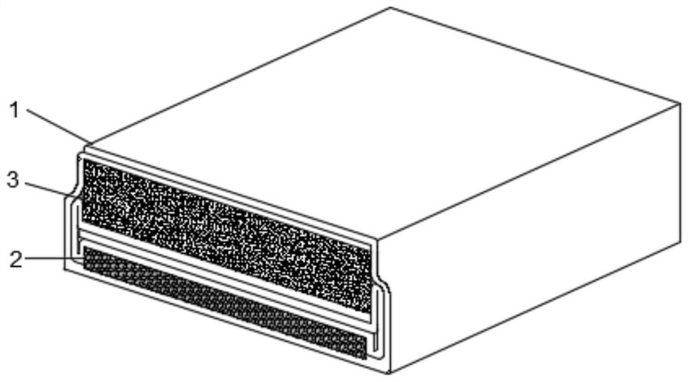
[0044] A composite bulletproof plate, such as image 3 As shown, it includes a tubular anti-crack fabric and a ceramic plate wrapped in the tubular anti-crack fabric. The coated ceramic plate is located in the middle of the tubular anti-crack fabric. The reserved end of the material backboard; the inner and outer surfaces of the tubular anti-crack fabric are coated with a hot-melt adhesive film, and a composite material backboard is arranged above the ceramic plate.

[0045] The composite material backboard is placed above the ceramic board and corresponds to the position of the ceramic board, and the reserved ends at both ends of the tubular anti-crack fabric are sequentially nested on the surface of the composite material backboard. The overall coverage of the ceramic plate and the composite material back plate is formed by the tubular anti-crack fabric, and the three-layer anti-crack fabric between the ceramic plate and the composite material back plate forms a transition l...

Embodiment 3

[0053] A composite bulletproof plate, such as Figure 4 As shown, it includes a tubular anti-crack fabric and a ceramic plate wrapped in the tubular anti-crack fabric. The coated ceramic plate is located in the middle of the tubular anti-crack fabric. The reserved end of the material backboard; the inner and outer surfaces of the tubular anti-crack fabric are coated with a hot-melt adhesive film, and a composite material backboard is arranged above the ceramic plate.

[0054] The composite material back plate is placed above the ceramic plate and corresponds to the position of the ceramic plate. Both ends of the tubular anti-crack fabric are folded and covered on the top of the ceramic plate, and then the composite material back plate is placed on the tubular anti-crack fabric. above the cracked fabric. The full coverage of the ceramic plate is formed by a tubular anti-crack fabric, while five layers of anti-crack fabric form the transition layer between the ceramic plate and...


PUM


Abstract

The invention provides a composite bulletproof plate and a coating method, the composite bulletproof plate comprises a first coating layer and a ceramic plate coated in the first coating layer, the inner surface and the outer surface of the first coating layer are both coated with hot melt adhesive films, a composite material back plate is arranged above the ceramic plate, and a transition layer is arranged between the composite material back plate and the ceramic plate. The transition layer and the first coating layer are integrally formed tubular crack arrest fabric. According to the bulletproof plate, the ceramic plate is coated with the tubular crack arrest fabric with the inner surface and the outer surface coated with the hot melt adhesive films, the forming process is simple, one-time coating of the hot melt adhesive films and the tubular crack arrest fabric can be achieved, and efficiency is high.

Description

technical field [0001] The invention belongs to the technical field of protective armor, and in particular relates to a composite bulletproof plate and a cladding method. Background technique [0002] Ceramic composite bulletproof boards are generally made of materials such as ceramics and polyethylene PE. The bulletproof principle is: when a bullet hits a bulletproof board, the bullet hits the ceramic layer first, and the bullet with huge kinetic energy hits the ceramic layer and the ceramics shatter. At the same time, the huge impact energy generated by the impact point will be transmitted to the surroundings to absorb the kinetic energy of the bullet. When the bullet passes through the ceramic layer, it has lost most of its kinetic energy. When the bullet reaches the polyethylene layer, the polyethylene consumes the kinetic energy of the bullet through stretching, and wraps the bullet and the shrapnel, so that the bullet will not damage the human body, thereby playing a r...

Claims


Application Information

Patent Timeline
Patent Type & Authority Applications(China)
IPC IPC(8): F41H5/04B32B27/02B32B27/34B32B27/12B32B9/00B32B9/04B32B27/32B32B3/04B32B7/12B29C65/02B29C65/00
CPCF41H5/0428B32B5/02B32B5/26B32B9/00B32B9/047B32B3/04B32B7/12B29C65/02B29C66/45B32B2262/0253B32B2262/0269B32B2307/558B32B2571/02
Inventor 赵玉芬齐长见宋磊磊郝露
Owner 中航装甲科技有限公司
Learn More