
Method for optimizing optical Isin machine system

An optical and optical circuit technology, applied in optics, nonlinear optics, optical computing equipment, etc., can solve the problems of mapping deviation and inability to obtain

Active Publication Date: 2021-07-30
SUN YAT SEN UNIV
View PDF4 Cites 0 Cited by
  • Summary
  • Abstract
  • Description
  • Claims
  • Application Information

AI Technical Summary

Problems solved by technology

However, in an actual system, under a fixed pump gain, the node optical field amplitude exhibits non-uniformity and randomness in the evolution of too long, which leads to a deviation in the mapping of the Ising Hamiltonian to the optical network, making the system The final oscillating state is not the lowest energy mode of the system, and the optimal result cannot be obtained

Method used


Image

  • Method for optimizing optical Isin machine system
  • Method for optimizing optical Isin machine system
  • Method for optimizing optical Isin machine system

Examples


Embodiment 1

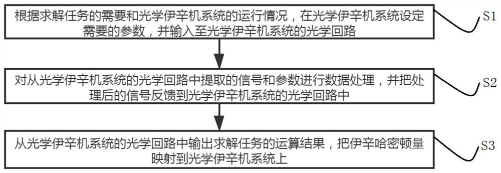
[0047] Such as figure 1 figure 2 and image 3 As shown, a method for optimizing an optical Ising machine system includes the following steps:

[0048] S1: According to the needs of solving tasks and the operation of the optical Ising machine system, set the required parameters in the optical Ising machine system and input them into the optical circuit of the optical Ising machine system;

[0049] S2: Perform data processing on the signal and parameters extracted from the optical circuit of the optical Ising machine system, and feed back the processed signal to the optical circuit of the optical Ising machine system;

[0050] S3: Output the calculation result of the solving task from the optical circuit of the optical Ising machine system, and map the Ising Hamiltonian to the optical Ising machine system.

[0051] In the above scheme, the optical circuit of the optical Ising machine system is used to realize the coupling between nodes and the gain of the node itself through...

Embodiment 2

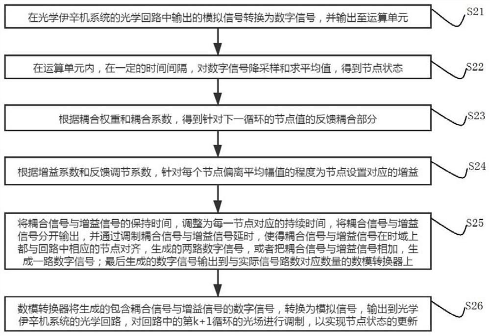
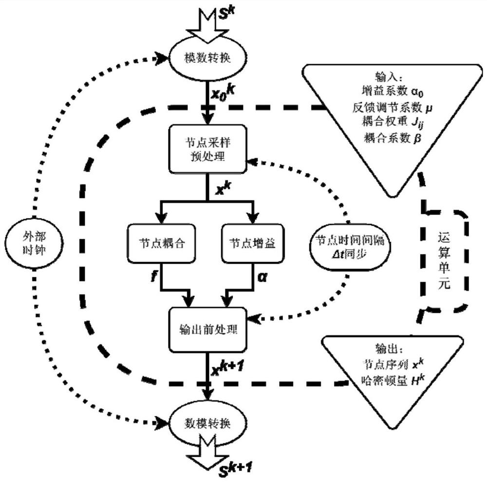
[0076] Such as Figure 4 and Figure 5 As shown, the node status based on this embodiment refers to such as Figure 4 As shown, under ideal or non-ideal conditions, the continuous light is modulated by the electro-optic modulator to form successively arranged small segments that are sequentially divided by a certain time interval Δt in the time domain and have different amplitudes. Among them, the node state x in the ideal node sequence i = a·σ i , where σ i =x i / |x i |∈{-1,+1}, then for all x i , with mean and variance of absolute values, respectively:

[0077]

[0078]

[0079] Therefore, the mapping to the Ising Hamiltonian can have:

[0080] H(x)=-∑ 1≤iπj≤N J ij x i x j =-a 2 ∑ 1≤iπj≤N J ij σ i σ j αH(σ)

[0081] In fact, the variance in the non-ideal node sequence each node x i = a·σ i +δ i , where δ i Indicates the degree to which the node deviates from the average value, and the mapped Hamiltonian at this time:

[0082] H(x)=-∑ 1≤iπj≤N J...


PUM


Abstract

The invention relates to a method for optimizing an optical Isin machine system, which comprises the following steps: setting required parameters in the optical Isin machine system according to the requirement of a solving task and the operation condition of the optical Isin machine system, and inputting the required parameters into an optical loop of the optical Isin machine system; performing data processing on the signals and parameters extracted from the Isin machine optical loop, and returning the processed signals to the Isin machine optical loop; outputting an operation result of a solving task from an optical loop of the Isin machine, and mapping the Isin Hamiltonian amount to an optical network of the Isin machine; using an Isin machine optical loop, performing data processing on signals and parameters to achieve coupling between nodes and gain of the nodes, wherein for the gain setting of the nodes, different gains are adaptively applied to the nodes according to the difference between the amplitude of each node and the average amplitude of all the nodes in each cycle, which is different from most methods that the same and fixed constant value is adopted for all nodes in most Isin machines.

Description

technical field [0001] The present invention relates to the field of Ising machines, and more particularly to a method for optimizing an optical Ising machine system. Background technique [0002] With the rise of concepts and technologies such as artificial intelligence and machine learning, more and more NP-Hard or NP-Compelte combinatorial optimization problems are involved in real life and scientific research, many of which can be reduced to Ising problems. That is, the solution is given by the given weight N nodes {σ i} The Ising Hamiltonian of the network system composed of: [0003] H(σ)=-∑ 1≤i≤j≤N J ij σ i σ j [0004] The minimum value of , and its corresponding {σ i}sequence. The current mainstream methods to solve the Ising problem mainly include simulated annealing based on traditional electronic computer, Hopfield neural network algorithm or automatic optimization method based on optical Ising machine. Based on traditional algorithms, when the scale o...

Claims


Application Information

Patent Timeline
Patent Type & Authority Applications(China)
IPC IPC(8): G06E3/00G06N10/00G02F1/39
CPCG06E3/005G06N10/00G02F1/39
Inventor 刘洁李振华余思远
Owner SUN YAT SEN UNIV
Learn More