Base coordinate system creation method for numerical control equipment group collaborative production line installation

A technology of base coordinate system and numerical control equipment, which is applied in the field of base coordinate system creation for the collaborative production line installation of numerical control equipment groups, can solve the problems of poor position accuracy, low installation efficiency, long heading span, etc.

Pending Publication Date: 2022-07-12
CHENGDU AIRCRAFT INDUSTRY GROUP
View PDF20 Cites 0 Cited by
  • Summary
  • Abstract
  • Description
  • Claims
  • Application Information

AI Technical Summary

Problems solved by technology

[0003] The installation of the traditional CNC equipment group collaborative production line is to use a ruler to measure the distance to determine the installation position of the CNC equipment group and adjust the parallel relationship. Not only the installation efficiency is low and the accuracy is poor, but also the single-axis CNC equipment and the Transfer equipment for precise adjustment of spatial position
With the development of digital measurement technology, spatial position measuring instruments can meet the high-efficiency and high-precision requirements for the installation of CNC equipment groups in coordination with the production line, but it is necessary to create the base coordinate system for production line installation. Prepare a reference CNC equipment, use the spatial position measuring instrument to measure the motion characteristic data of the CNC equipment, determine the coordinate system of the CNC equipment in the coordinate system of the measurement system, according to the position and orientation of the reference CNC equipment coordinate system in the digital model and the base coordinate system of the production line relationship, and then determine the base coordinate system of the production line in the coordinate system of the measurement system. The disadvantage of this method is that the size of the reference CNC equipment of the CNC equipment group is small, and the cooperative production line of the CNC equipment group generally has a long heading span, and the equipment foundation The actual installation position of the buried plate is less accurate than the theoretical position of the digital model. The base coordinate system created by this method is used as a reference to install the rest of the equipment in the production line. The case of edge interference

Method used


Image

  • Base coordinate system creation method for numerical control equipment group collaborative production line installation
  • Base coordinate system creation method for numerical control equipment group collaborative production line installation
  • Base coordinate system creation method for numerical control equipment group collaborative production line installation

Examples


Embodiment 1

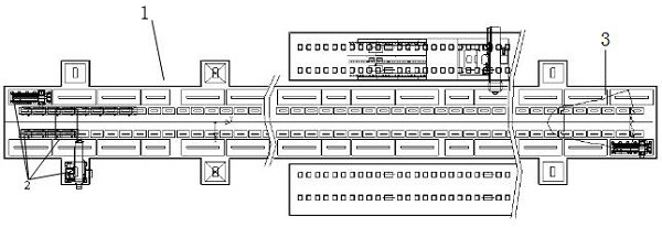
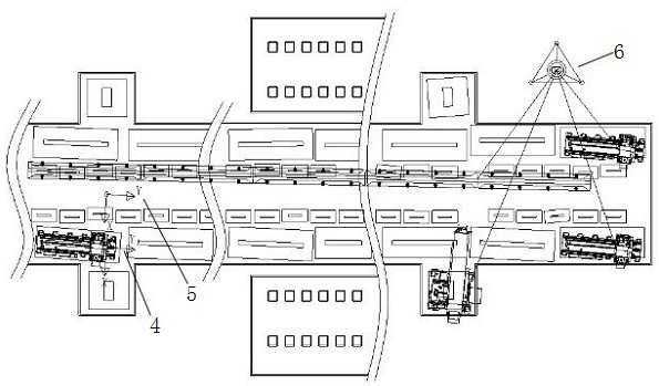
[0035] refer to Figure 1 to Figure 5 , this embodiment provides a method for creating a base coordinate system for the installation of a collaborative production line of a numerical control equipment group. This method takes the numerical control equipment group collaborative system production line 1 as an application scenario as an embodiment, and creates a base coordinate system for different types of production lines. Compared with the existing method of creating the base coordinate system 5 with the reference numerical control equipment 4 as a reference, the digital adjustment of the 2 poses of the numerical control equipment with the number of axes avoids the situation that the equipment at the far end of the production line is installed outside the foundation embedded board .

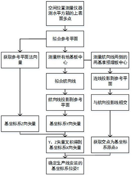
[0036] The specific implementation process of the present invention is as follows figure 1 shown, including the following steps:

[0037] 1) use the level meter 8 to level the upper surface of ...

Embodiment 2

[0046] On the basis of Embodiment 1, in order to better realize the method of the present invention, refer to Figure 4 scene model and Figure 5 Geometric model, and further describe the step 1) in detail.

[0047] The specific method of fitting the reference plane 11 of the production line is as follows: the spatial position measuring instrument 6 measures the coordinates h (x i ,y i ,z i ), simplify the general formula plane equation (1) to formula (2), and then convert it to the equation of formula (3), and use the plane to fit the least squares model, that is, to obtain the smallest variance of the distances from all points to the plane, use The multiple linear regression least squares estimation model (5) and the optimal solution matrix algorithm (6) are used to solve the optimal general plane equation parameters b(a 0 , a 1 , a 2 ), and then obtain the equation of the reference plane P of the production line.

[0048] Ax+By+Cz+D=0 Formula (1)

[0049]

[0050...


PUM


Abstract

The invention discloses a base coordinate system creating method for numerical control equipment group collaborative production line installation, which comprises the following steps of: measuring coordinates of a plurality of points on the upper surface of a square box leveled by a gradienter by a spatial position measuring instrument, fitting a reference plane of a production line, measuring coordinates of center points of all foundation embedded plates on site, and establishing a base coordinate system; fitting a course line of the production line; projecting the course line to a reference plane to serve as a Y-direction vector of the base coordinate system, obtaining a normal vector of the reference plane to serve as a Z-direction vector of the base coordinate system, and performing cross product operation on the Y vector and the Z vector to obtain an X-direction vector of the base coordinate system; measuring coordinates of center points of foundation embedded plates of two pieces of reference equipment on two sides of the course line, projecting a straight line formed by the two points to a reference plane, and enabling the straight line to intersect with the projection of the course line to obtain an original point of a base coordinate system; and determining the pose T of the base coordinate system by using the direction vector and the original point. The method can effectively determine the optimal standard for installation of the production line, and is used for digital accurate installation and adjustment of numerical control equipment groups.

Description

technical field [0001] The invention relates to the technical field of numerical control equipment installation and adjustment, in particular to a method for creating a base coordinate system for the collaborative production line installation of numerical control equipment groups. Background technique [0002] At present, with the rapid development of digital factory technology, the digital equipment system has evolved from the previous mode of single CNC equipment for parts processing to the current CNC equipment group collaborative production line for large parts pose adjustment, precise assembly and finishing. Mode, the assembly and processing coordinate data of components is not based on the equipment coordinate system of a single CNC equipment, but is based on the common coordinate system of the production line, that is, the base coordinate system. The coordinated movement of the CNC equipment group under the common coordinate system controls the pose of the component a...

Claims


Application Information

Patent Timeline
Patent Type & Authority Applications(China)
IPC IPC(8): G05B19/408
CPCG05B19/4086G05B2219/35356Y02P90/02
Inventor 申少泽李国进王飞周文强黄中平国宏达李步金
Owner CHENGDU AIRCRAFT INDUSTRY GROUP
Why Eureka
Try Eureka