
Efficient compact heat exchanger and heat exchange amount calculation method

A heat exchanger, compact technology, applied in the direction of heat exchanger shell, indirect heat exchanger, heat exchanger type, etc., can solve the problems of uneven heat transfer, complicated calculation process, low heat transfer coefficient of fluid inside and outside the tube, etc.

Active Publication Date: 2021-07-30
NANJING UNIV OF AERONAUTICS & ASTRONAUTICS
View PDF6 Cites 0 Cited by
  • Summary
  • Abstract
  • Description
  • Claims
  • Application Information

AI Technical Summary

Problems solved by technology

Existing heat exchangers only use fans to force the intercooling fluid to flow, and this single forced flow mode is relatively slow; the copper tube in the core structure of the existing heat exchanger is not provided with a turbulent flow mechanism for the hot fluid. The heat transfer coefficient of the fluid inside and outside the tube is low and the heat transfer is uneven; the method of calculating the heat transfer amount of the existing heat exchanger is usually to know the structure and size parameters of the heat exchanger core, and calculate the air circulation area, air front wind Area, heat side porosity, heat transfer area (baffle, circular tube heat transfer area), thermophysical parameters, convective surface heat transfer coefficient, total heat transfer coefficient and number of heat transfer units. Heater efficiency and hot / cold fluid outlet temperature, and finally, calculate the heat exchanger heat exchanger
This method of heat transfer calculation is only applicable to heat exchangers with known heat exchanger core structure, and the calculation process is complicated

Method used


Image

  • Efficient compact heat exchanger and heat exchange amount calculation method
  • Efficient compact heat exchanger and heat exchange amount calculation method
  • Efficient compact heat exchanger and heat exchange amount calculation method

Examples


Embodiment Construction

[0024] The following will clearly and completely describe the technical solutions in the embodiments of the present invention with reference to the accompanying drawings in the embodiments of the present invention. Obviously, the described embodiments are only some, not all, embodiments of the present invention. Based on the embodiments of the present invention, all other embodiments obtained by persons of ordinary skill in the art without making creative efforts belong to the protection scope of the present invention.

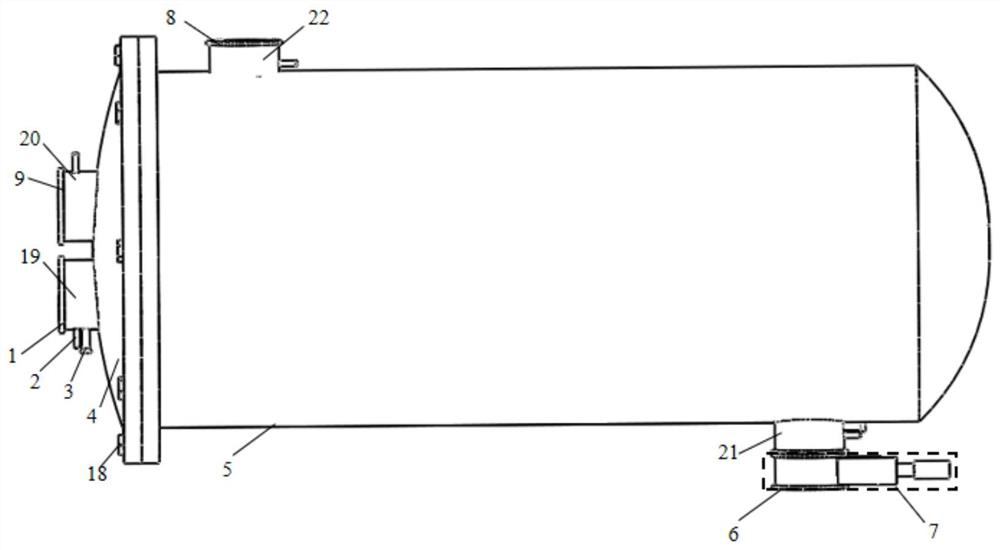
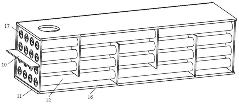
[0025] refer to Figure 1-Figure 5b , this embodiment provides a high-efficiency compact heat exchanger, including: hot fluid inlet 1, thermometer 2, flow meter 3, flange end cover 4, heat exchanger shell 5, cold fluid inlet 6, volumetric compressor 7 , cold fluid outlet 8, hot fluid outlet 9, hot fluid partition 10, cold fluid baffle 11, copper tube 12, cold fluid injector 13, sealed chamber 14, exhaust fan 15, sealing plate 16, vortex generator 17 , fasteni...


PUM


Abstract

The invention discloses an efficient compact heat exchanger and a heat exchange amount calculation method. The efficient compact heat exchanger comprises a hot fluid inlet, a thermometer, a flowmeter, a flange end cover, a heat exchanger shell, a cold fluid inlet, a volumetric air compression device, a cold fluid outlet, a hot fluid outlet, a hot fluid partition plate, a cold fluid baffle, a red copper pipe, a cold fluid ejector, a sealing cavity, an exhaust fan, a sealing plate, a vortex generator, a fastening nut, a hot fluid inlet pipeline, a hot fluid outlet pipeline, a cold fluid inlet pipeline and a cold fluid outlet pipeline. The heat exchanger has the advantages of being compact in structure and high in heat exchange efficiency. The heat exchange amount calculation method has the advantages of being concise in calculation process, simple in formula form, high in universality and high in calculation accuracy.

Description

technical field [0001] The invention belongs to the technical field of general thermal equipment and specifically designs a high-efficiency compact heat exchanger and a calculation method for heat transfer. Background technique [0002] Heat exchanger, also known as heat exchanger, is a device that transfers heat from one medium to another. It is widely used in various fields such as aerospace, refrigeration, air conditioning, chemical industry, energy, machinery and transportation. However, the heat exchange capacity of the heat exchanger determines that the heat exchanger should meet certain heat exchange efficiency requirements. Therefore, the type and flow mode of the flow medium in the heat exchanger, the structure of the core body of the heat exchanger and the calculation method of the heat transfer are the key links to check whether the design of the heat exchanger and the calculation results of the heat transfer meet the requirements. Existing heat exchangers only u...

Claims


Application Information

Patent Timeline
IPC IPC(8): F28D7/16F28F9/22F28F13/12F28F27/00G06F30/20G06F119/08
CPCF28D7/16F28F9/22F28F13/12F28F27/00G06F30/20F28F2009/224G06F2119/08
Inventor 李冲方贤德罗祖分
Owner NANJING UNIV OF AERONAUTICS & ASTRONAUTICS
Learn More