
Axial force conical surface thrust structure for high-speed heavy-load helical gear transmission system

A transmission system and helical gear technology, which is applied to transmission parts, belts/chains/gears, mechanical equipment, etc., can solve the problems of high operating temperature, thrust bearings not suitable for pinion operating conditions, and oil film rupture of conical thrust rings And other issues

Inactive Publication Date: 2021-07-30
中国船舶重工集团公司第七0三研究所
View PDF14 Cites 0 Cited by
  • Summary
  • Abstract
  • Description
  • Claims
  • Application Information

AI Technical Summary

Problems solved by technology

[0003] The purpose of the present invention is to provide a solution to the high-speed and heavy-duty helical gear transmission. The thrust bearing cannot be applied to the high linear speed and high-load operating conditions of the pinion shaft, and due to the large transmission torque of the helical gear under heavy load conditions The axial force component of the pinion, the stress deformation of the pinion due to bending and torsion coupling, and the external axial load are too large, which cause technical problems such as oil film rupture of the conical thrust ring, high operating temperature, and even failure of the conical thrust structure. Axial force cone thrust structure for high-speed heavy-duty helical gear transmission system

Method used


Image

  • Axial force conical surface thrust structure for high-speed heavy-load helical gear transmission system
  • Axial force conical surface thrust structure for high-speed heavy-load helical gear transmission system
  • Axial force conical surface thrust structure for high-speed heavy-load helical gear transmission system

Examples


Embodiment Construction

[0016] The present invention will be described in more detail below with reference to the accompanying drawings:

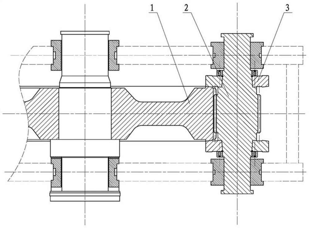
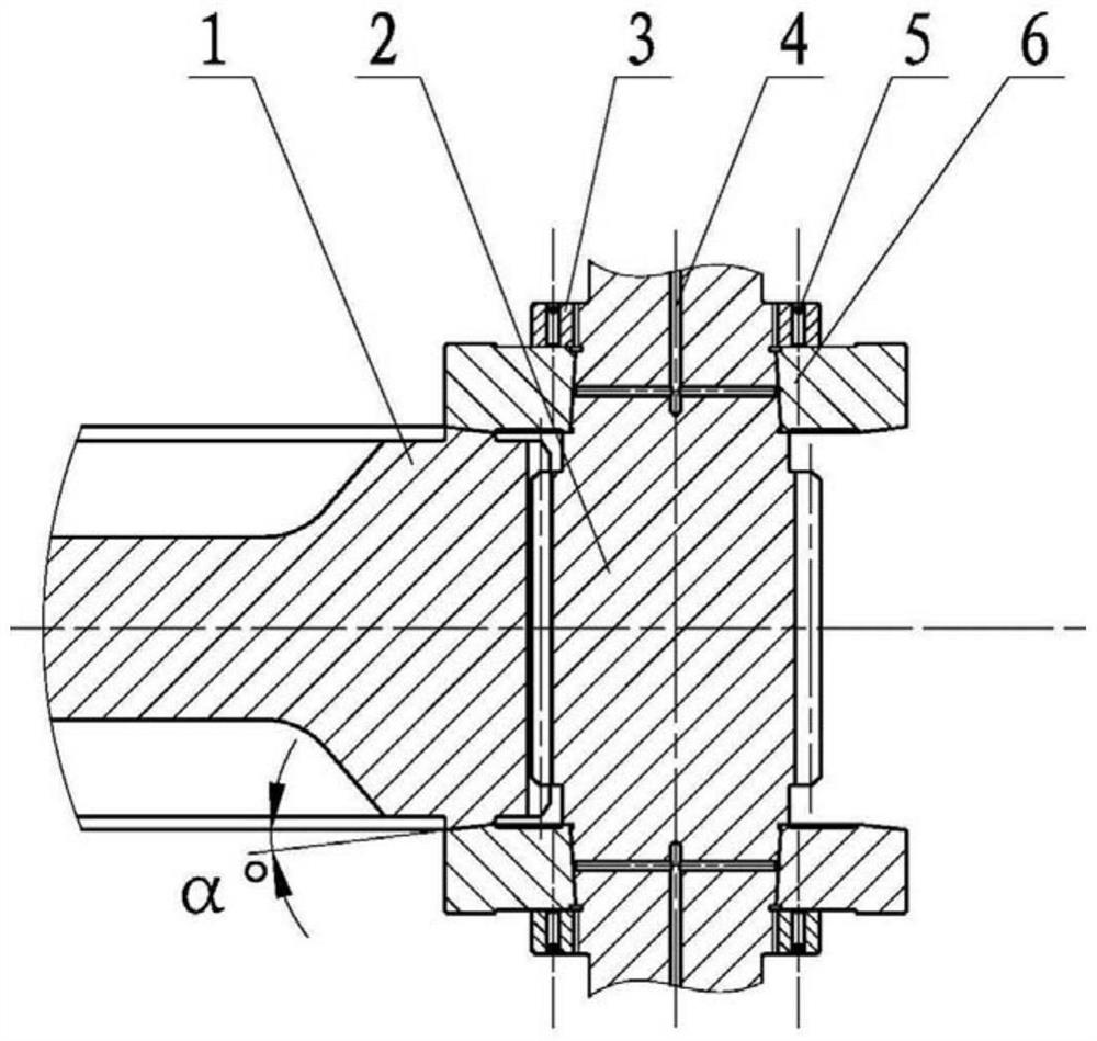
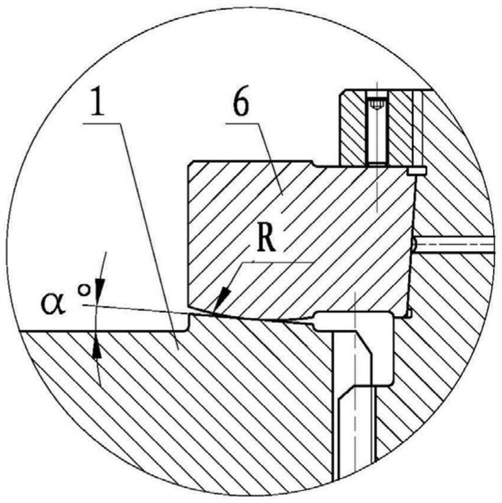
[0017] Combine Figure 1-3 The axial force cone surface thrust structure of the present invention is composed of a low speed large gear 1, a high speed pinion 2, an axial lock nut 3, a high pressure oil passage 4, a tightening screw 5, a cone surface push ring 6. The cone surface push ring 6 is a tapered structure, fitted to the outer diameter portion of the high speed pinion 2 tapered surface, and the high-pressure oil passage 4 is provided inside the high speed pinion, and the high pressure oil pump is passed through the high pressure oil pump. Injecting the insertion of the jaw high pressure oil passage 4, the inner diameter of the cone surface push loop 6 is large, and the tapered push loop 6 is tightly contacted with the high-speed gear shaft by mating the tightening axis 6, and since the high pressure oil generates internal pressure. The inner diameter of the con...


PUM


Abstract

The invention aims at providing an axial force conical surface thrust structure for a high-speed heavy-load helical gear transmission system. The structure comprises a high-speed pinion and a conical surface ring, wherein an inner hole of the conical surface ring is a conical surface, the inner hole of the conical surface ring sleeves the outer diameter of a conical surface of the high-speed pinion, a high-pressure oil channel is formed in the high-speed pinion, the high-pressure oil channel comprises a transverse oil way and a longitudinal oil way which communicate with each other, the longitudinal oil way communicates with an oil way of a high-pressure oil pump, and the transverse oil way communicates with the face, matched with the high-speed pinion, of the conical surface ring. The conical surface ring is subjected to arc modification along the conical contact face, so that the allowable minimum oil film thickness of the conical surface thrust structure is increased, the axial force bearing capacity is improved, and stable operation of the conical surface thrust structure under high speed and high load is guaranteed. The conical surface ring and a high-speed gear shaft are installed through a conical surface hydraulic tensioning structure, so that the bearing capacity of the conical surface ring is improved, the reliability of structural operation is enhanced, meanwhile, the high-precision assembly relation is guaranteed, the structure is compact, and the disassembly and assembly are convenient.

Description

Technical field [0001] The present invention relates to a ramp gear drive system, specifically a thrust structure of a torched gear drive system. Background technique [0002] In the gear transmission of high-speed overload mechanical, a tide gear is often used to reduce noise and increase transfer torque. Since the slope gear drive is more simple, the hard tooth grinding structure is particularly applicable to the advantages of simple structure, convenient manufacture, etc. However, due to the impact of the spiral angle, the transfer torque between the pinion and the large gear produces a large axial force component, and the axial force component usually must be transmitted to the gearbox housing through the gear, axis, and axial bearing. In order to avoid the generating axial force component during the working process, a tapered gear with a tapered thrust device (also known as thrust cone) can be used (eg figure 1 Indicated). Conventional cone surface thrust structures are ofte...

Claims


Application Information

Patent Timeline
Patent Type & Authority Applications(China)
IPC IPC(8): F16H57/023F16H57/021
CPCF16H57/023F16H57/021F16H2057/02095
Inventor 李硕黄莹莹王勇帆左晓镭王苏鸣安文迪
Owner 中国船舶重工集团公司第七0三研究所
Learn More