
Pressure measuring device and method based on quadrature phase rapid demodulation and intensity compensation

An intensity compensation and quadrature phase technology, which is applied in the field of optical non-contact pressure real-time measurement devices, can solve the problems of the influence of signal strength, the influence of demodulation cannot be eliminated, and it is difficult to achieve fast demodulation, and the effect of reducing influence can be achieved.

Active Publication Date: 2021-07-27
TIANJIN UNIV
View PDF9 Cites 0 Cited by
  • Summary
  • Abstract
  • Description
  • Claims
  • Application Information

AI Technical Summary

Problems solved by technology

(3) Multi-wavelength phase demodulation method, which is only applicable to single-cavity F-P sensors, and it cannot eliminate the influence of multiple cavities on demodulation, such as F-P sensors based on micro-electromechanical systems (MEMS) technology
But for real-time measurement of pressure, the scan frequency of OSA must be high, and it is difficult to achieve fast demodulation
[0004] Current quadrature phase demodulation devices are generally affected by factors such as light source power fluctuations, optical path loss changes, or polarization state changes that affect the signal strength.
Since the quadrature phase demodulation is based on the change of signal strength to extract the phase, the strength interference will affect the accuracy of the demodulation result, which greatly limits the practical application of the quadrature phase demodulation device

Method used


Image

  • Pressure measuring device and method based on quadrature phase rapid demodulation and intensity compensation
  • Pressure measuring device and method based on quadrature phase rapid demodulation and intensity compensation
  • Pressure measuring device and method based on quadrature phase rapid demodulation and intensity compensation

Examples


Embodiment Construction

[0022] The wide-spectrum light source 1 is an SLED light source or an ASE light source with a center wavelength of 1550 nm and a spectral width of 70-80 nm. Embodiments of the present invention will be further described in detail below in conjunction with the accompanying drawings. The descriptions about the implementations are only exemplary, and should not be construed as limiting the present invention.

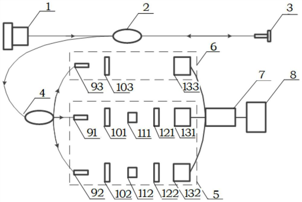
[0023] Such as figure 1 Shown is a schematic diagram of a real-time pressure measurement device based on quadrature phase fast demodulation and intensity compensation. The device includes: wide-spectrum (ASE or SLED) light source 1, optical fiber circulator 2, F-P pressure sensor 3, optical fiber 1×3 coupler 4, low coherence interferometer 5, intensity compensator 6, data acquisition card 7. Signal processing unit 8. Optical fiber collimator, polarizer, birefringent crystal block, analyzer, photodetector. The low-coherence interferometer 5 specifically includes two optic...


PUM


Abstract

The invention discloses a pressure measuring device and method based on quadrature phase rapid demodulation and intensity compensation. The pressure measuring device comprises a wide-spectrum light source (1), an optical fiber circulator (2), a Fabry-Perot (F-P) pressure sensor (3), an optical fiber 1 * 3 coupler (4), a low-coherence interferometer (5), an intensity compensator (6), a photoelectric detector (13), a data acquisition card (7) and a signal processing unit (8). During measurement, the F-P pressure sensor (3) is used for performing pressure sensing and constructing a quadrature phase signal, real-time intensity compensation is used for reducing the influence of external interference factors on a demodulation result, a phase is quickly and inversely calculated through a four-quadrant arc tangent algorithm subjected to level compensation, and the phase is converted into a pressure value in real time through calibration-fitting. Compared with the prior art, the signal demodulation of the F-P pressure sensor (3) containing a plurality of cavities can be realized, the influence of signal intensity fluctuation on a demodulation result can be greatly reduced, and the stability and the accuracy of a demodulation system are remarkably improved.

Description

technical field [0001] The invention relates to an optical non-contact pressure real-time measurement device, in particular to a pressure real-time measurement device and a measurement method based on quadrature phase fast demodulation and intensity compensation. Background technique [0002] Real-time pressure measurement is one of the necessary means to detect the operation of equipment, which is challenging in the pressure measurement of aeroengines or shock waves. Due to the characteristics of small size, light weight, high sensitivity and anti-electromagnetic interference, the F-P sensor is considered as one of the potential sensors for pressure detection under harsh conditions. However, for signals that need to be measured in real time, such as pressure signals, fast demodulation of the F-P sensor is key. [0003] Existing fast demodulation methods include: (1) Intensity demodulation method, which realizes fast demodulation of F-P sensors, but its demodulation result ...

Claims


Application Information

Patent Timeline
IPC IPC(8): G01L11/02G01L1/24G01L19/00
CPCG01L11/02G01L1/242G01L19/00
Inventor 王双刘铁根李致远江俊峰刘琨刘文燕张鹏
Owner TIANJIN UNIV
Learn More