Method for purifying high-concentration N2F2 in large-flow NF3 electrolysis gas
A purification method and electrolytic gas technology, which is applied in the field of NF3 purification, can solve the problems of low adsorption efficiency, high energy consumption, and small electrolytic gas treatment capacity, and achieve the effects of less power consumption, reduced safety risks, and prolonged residence time
- Summary
- Abstract
- Description
- Claims
- Application Information
AI Technical Summary
Problems solved by technology
Method used
Image
Examples
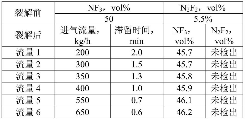
Embodiment 1
[0028] A pyrolysis tower with a diameter of 800mm and a height of 9000mm is selected for use; nickel Pall rings (nickel purity is 99.5wt%) are used as the internal packing of the pyrolysis tower with a specification or nominal size of 25mm, and the filling height of the packing is 7000mm, and the specific surface area of the packing is 300m 2 / m 3 ; Choose 4 electromagnetic heating devices to heat the cracking tower, and the 4 electromagnetic heating devices are evenly distributed in the axial direction of the cracking tower.
[0029] The above cracking tower is directly connected with the electrolyzer, and the NF output from the electrolyzer is 3The content is 50vol% and N 2 f 2 5.5vol% NF 3 When the electrolytic gas is purified:
[0030] NF 3 The electrolytic gas enters the pyrolysis tower from the bottom of the tower at the inlet flow rate of 200kg / h, 300kg / h, 350kg / h, 400kg / h, 550kg / h and 650kg / h respectively. 3 During the process of electrolysis gas flowing from t...
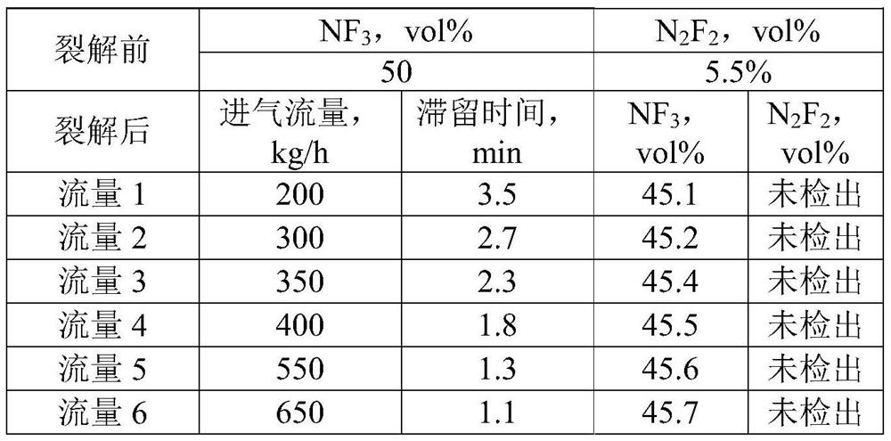
Embodiment 2
[0035] A pyrolysis tower with a diameter of 1000mm and a height of 10000mm is selected; nickel Pall rings with a specification or nominal size of 25mm (the purity of nickel is 99.5wt%) are used as the internal packing of the pyrolysis tower, and the filling height of the packing is 8000mm, and the specific surface area of the packing is 300m 2 / m 3 ; Choose 4 electromagnetic heating devices to heat the cracking tower, and the 4 electromagnetic heating devices are evenly distributed in the axial direction of the cracking tower.
[0036] The above cracking tower is directly connected with the electrolyzer, and the NF output from the electrolyzer is 3 The content is 50vol% and N 2 f 2 5.5vol% NF 3 When the electrolytic gas is purified:
[0037] NF 3 The electrolytic gas enters the pyrolysis tower from the bottom of the tower at the inlet flow rate of 200kg / h, 300kg / h, 350kg / h, 400kg / h, 550kg / h and 650kg / h respectively. 3 During the process of electrolysis gas flowing from...
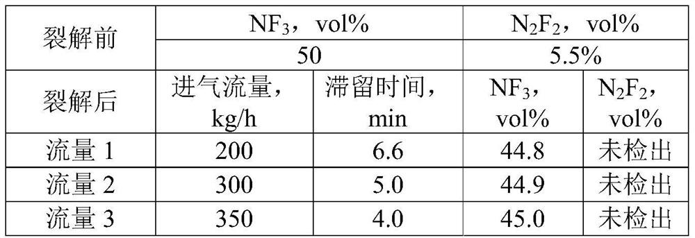
Embodiment 3
[0042] A pyrolysis tower with a diameter of 1200mm and a height of 13000mm is used; nickel Pall rings (nickel purity of 99.5wt%) are used as the internal packing of the pyrolysis tower with a specification or nominal size of 25mm, and the filling height of the packing is 10000mm, and the specific surface area of the packing is 300m 2 / m 3 ; Choose 4 electromagnetic heating devices to heat the cracking tower, and the 4 electromagnetic heating devices are evenly distributed in the axial direction of the cracking tower.
[0043] The above cracking tower is directly connected with the electrolyzer, and the NF output from the electrolyzer is 3 The content is 50vol% and N 2 f 2 5.5vol% NF 3 When the electrolytic gas is purified:
[0044] NF 3 The electrolytic gas enters the pyrolysis tower from the bottom of the tower at the inlet flow rate of 200kg / h, 300kg / h, 350kg / h, 400kg / h, 550kg / h and 650kg / h respectively. 3 During the process of electrolysis gas flowing from the botto...
PUM
| Property | Measurement | Unit |
|---|---|---|
| diameter | aaaaa | aaaaa |
| height | aaaaa | aaaaa |
| height | aaaaa | aaaaa |
Abstract
Description
Claims
Application Information
 - Generate Ideas
- Intellectual Property
- Life Sciences
- Materials
- Tech Scout
- Unparalleled Data Quality
- Higher Quality Content
- 60% Fewer Hallucinations
Browse by: Latest US Patents, China's latest patents, Technical Efficacy Thesaurus, Application Domain, Technology Topic, Popular Technical Reports.
© 2025 PatSnap. All rights reserved.Legal|Privacy policy|Modern Slavery Act Transparency Statement|Sitemap|About US| Contact US: help@patsnap.com


