
Bridge or house building support friction part convenient to rotate or slide and preparation method thereof

A technology for friction parts and construction, which is applied in bridge construction, architecture, bridges, etc., can solve the problems of restricting the use effect of bearings and increasing costs, and achieve the effects of ensuring cladding quality, reducing production costs, and ensuring spherical radians

Inactive Publication Date: 2021-07-20
HENGSHUI ZHONGJIAO XINDE ENG RUBBLE & PLASTIC
View PDF0 Cites 0 Cited by
  • Summary
  • Abstract
  • Description
  • Claims
  • Application Information

AI Technical Summary

Problems solved by technology

The above two processes, in addition to adding a lot of extra cost, also seriously restrict the use effect of the support

Method used


Image

  • Bridge or house building support friction part convenient to rotate or slide and preparation method thereof
  • Bridge or house building support friction part convenient to rotate or slide and preparation method thereof
  • Bridge or house building support friction part convenient to rotate or slide and preparation method thereof

Examples


Embodiment 1

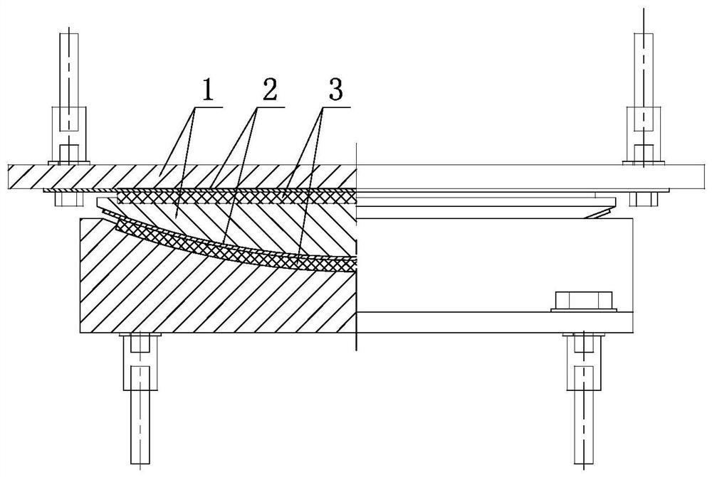
[0043] The overall structure of this embodiment is as figure 1 As shown, it includes components such as an upper bearing plate, a lower bearing plate, and a spherical crown plate, and an organic material slide plate 3 is arranged between the spherical crown plate and the upper bearing plate and between the spherical crown plate and the lower bearing plate , the friction surface opposite to the organic material slide plate 3 includes a substrate 1 and an anti-rust and wear-resistant layer 2, and the anti-rust and wear-resistant layer 2 is arranged on the outer surface of the base 2 by laser cladding. The surface of the base body 1 of the upper support plate opposite to the organic material slide plate 3 is laminated with a flat anti-rust and wear-resistant layer by laser cladding, and the surface of the base body 1 of the spherical crown plate opposite to the organic material slide plate 3 is laser clad. The method is compounded with an anti-rust and wear-resistant layer with a...

Embodiment 2

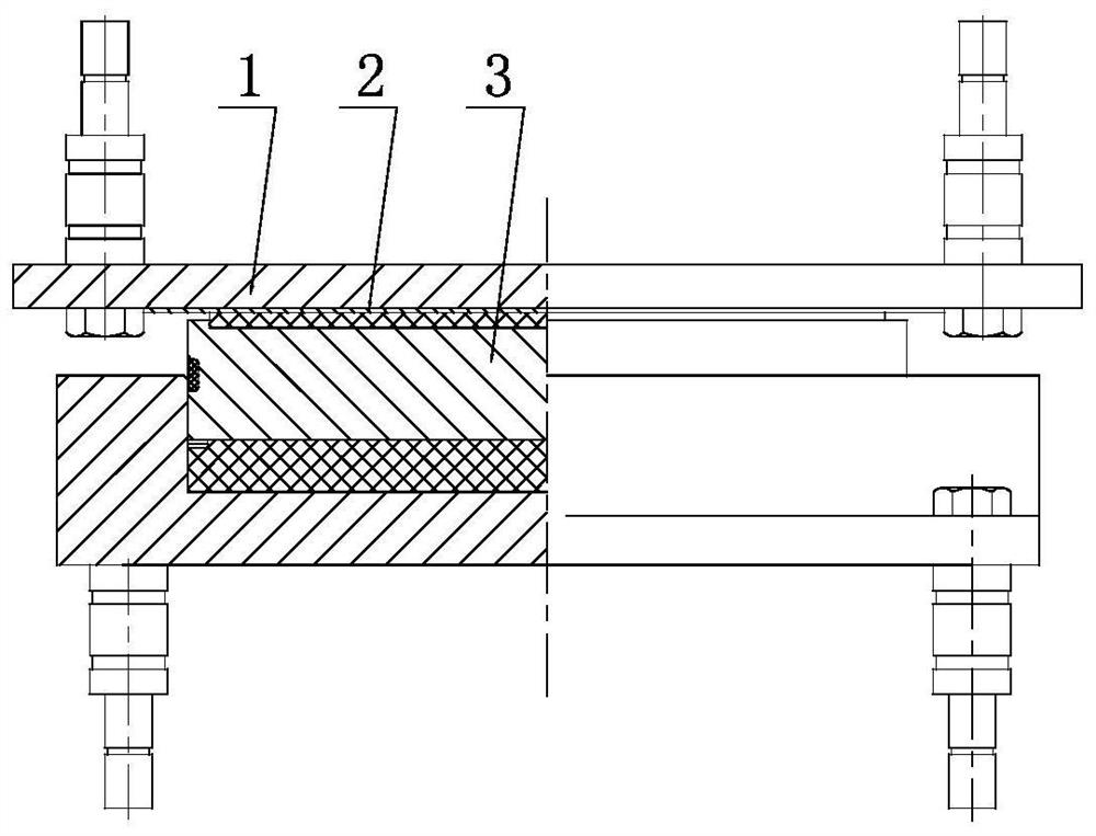
[0060] The overall structure of this embodiment is as figure 2 As shown, it includes components such as an upper steel plate, a lower steel plate, and an intermediate plate. An organic material slide plate 3 is arranged on the upper surface of the intermediate plate. The grinding layer 2 and the anti-rust and wear-resistant layer 2 are arranged on the outer surface of the substrate 2 by means of laser cladding.

[0061] The preparation method of this embodiment is the same as that of Example 1.

Embodiment 3

[0063] The overall structure of this embodiment is as image 3 As shown, it includes components such as an upper support plate, a lower support plate, and an intermediate plate. An organic material slide plate 3 is arranged on the upper surface of the intermediate plate, and the friction surface of the lower part of the upper support plate opposite to the organic material slide plate 3 includes Substrate 1, anti-rust and wear-resistant layer 2, the anti-rust and wear-resistant layer 2 is arranged on the outer surface of the substrate 2 by laser cladding.

[0064] The preparation method of this embodiment is the same as that of Example 1.


PUM

PropertyMeasurementUnit
Thicknessaaaaaaaaaa
Granularityaaaaaaaaaa

Abstract

The invention belongs to manufacturing of bridge supports, and particularly relates to a bridge or house building support friction part convenient to rotate or slide and a preparation method thereof. The friction part comprises an organic material sliding plate and a friction surface opposite to the organic material sliding plate, the friction surface comprises a base body and an anti-rust wear-resistant layer, and the anti-rust wear-resistant layer is arranged on the outer surface of the base body in a laser cladding mode. The problems that in the prior art, adjacent structural layers are not tightly matched, and the manufacturing cost is high are solved, and the beneficial effects that the adjacent structural layers are tightly matched, environmental pollution is reduced, and the machining efficiency is improved are achieved.

Description

technical field [0001] The invention belongs to the manufacture of bridges or building supports, in particular to a friction part of a bridge or a building building support that is easy to realize rotation or sliding and a preparation method thereof. Background technique [0002] The bearing of a bridge or a building is an important part connecting the superstructure and the substructure of a bridge or a building. In addition to bearing vertical loads such as dead loads and live loads transmitted by the superstructure and lateral loads such as earthquakes and winds, it must also adapt to live loads and The horizontal displacement of the upper structure caused by temperature changes and the displacement of the fulcrum angle caused by deflection. Supports commonly used at this stage include plate bearings, basin bearings, spherical bearings, cylindrical bearings, hyperboloid bearings, friction pendulum bearings, etc. [0003] In order to ensure the rotation and sliding requir...

Claims


Application Information

Patent Timeline
IPC IPC(8): E01D19/04C23C24/10
CPCC23C24/106E01D19/04E01D19/048
Inventor 赵杰王国兴冷峻峰李彦春王飞高建华
Owner HENGSHUI ZHONGJIAO XINDE ENG RUBBLE & PLASTIC
Learn More