Numerical control machine tool facilitating water drainage

A technology of CNC machine tools and machine bodies, applied in metal processing machinery parts, maintenance and safety accessories, metal processing equipment, etc., can solve problems such as reduced performance, blockage of coolant, and inability to cool in time, so as to facilitate cooling work, reduce blocking effect

Inactive Publication Date: 2021-07-16
冯玉金
View PDF0 Cites 4 Cited by
  • Summary
  • Abstract
  • Description
  • Claims
  • Application Information

AI Technical Summary

Problems solved by technology

[0005] Aiming at the deficiencies of the prior art, the present invention provides a convenient drainage type CNC machine tool, which solves the problem that a large amount of debris will be generated during the machining of the CNC machine tool, and these debris are easy to accumulate and block the cooling liquid, making the The entire water circulation is not smooth, and it cannot be cooled in time, which affects the efficiency and quality of machining, and reduces the problem of performance

Method used


Image

  • Numerical control machine tool facilitating water drainage
  • Numerical control machine tool facilitating water drainage
  • Numerical control machine tool facilitating water drainage

Examples


Embodiment example 1

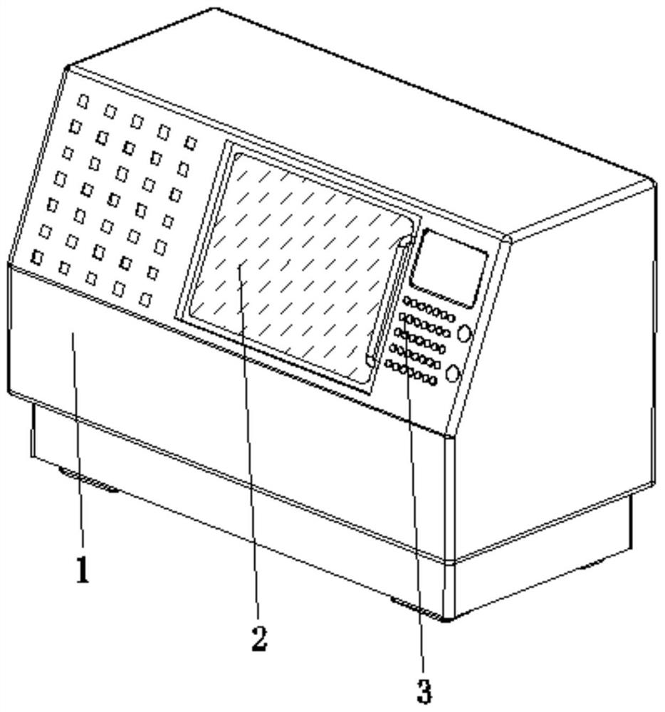
[0029] see Figure 1-6 , the present invention provides a technical solution: a convenient drainage type CNC machine tool, including a housing 1, a sliding door 2, and an operating surface 3, the sliding door 2 is arranged on one side of the surface of the housing 1 and is located in the center, and the operating surface 3 Set on the surface side of the housing 1 and close to the sliding door 2;

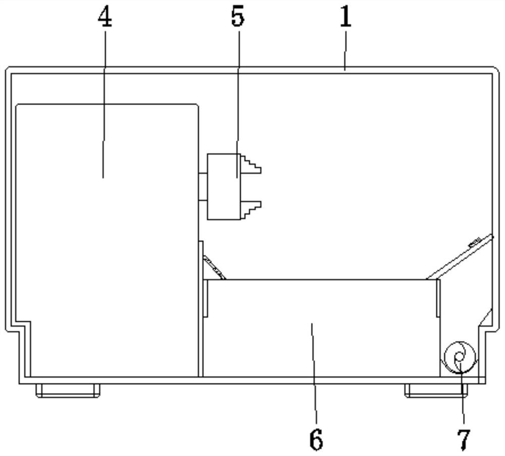
[0030] The inside of the housing 1 is provided with a body 4, a clamping drive mechanism 5, a water storage device 6, and a jiaolong chip removal mechanism 7. Extending to the outside, the water storage device 6 is arranged at the bottom of the inner wall of the housing 1 and is located at the position of the body 4, and the Jiaolong chip removal mechanism 7 is arranged at the bottom of the inner wall of the housing 1 and is located at the position of the water storage device 6, which can remove debris Turn it over in time to reduce the clogging caused by accumulation, which is cond...

Embodiment example 2

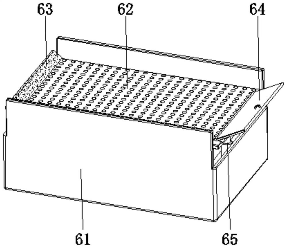
[0034] By setting the sieve plate 621, the baffle plate 622, the slide plate 623, the float 624, and the piercing device 625, when the cooling liquid smoothly flows down from the leakage hole on the sieve plate 621, the drainage is smooth, thereby reducing its own weight. Under the joint action of the buoyancy and the elastic telescopic device 65, the filter device 62 rises and circulates like this, so as to achieve the purpose of preventing clogging and make the drainage smooth.

Embodiment example 3

[0036]The piercing device 625 is provided with a support rod 6251, a conical top cap 6252, and a bar-shaped hole 6253. The bottom end of the support rod 6251 is fixedly connected to the top of the slide plate 623, and the top of the inner wall of the conical top cap 6252 is fixedly connected to the top of the support rod 6251. , the strip-shaped holes 6253 are opened on the surface of the conical top cap 6252, and the strip-shaped holes 6253 are evenly distributed on the surface of the conical top cap 6252. When it is lifted up, the coolant flows downward from the strip hole 6253 in time, and the accumulated debris is turned over to leak out of the leak hole on the sieve plate 621, allowing the coolant to flow out smoothly, thereby achieving the effect of facilitating drainage.


PUM


Abstract

The invention discloses a numerical control machine tool facilitating water drainage. The numerical control machine tool comprises a shell, a sliding door and an operation face, wherein the sliding door is arranged at one side of the surface of the shell and located in the center, the operation face is arranged at the side, close to the sliding door, of the surface of the shell, and a machine body, a clamping driving mechanism, a water storage device and an auger chip removal mechanism are arranged in the shell; and the machine body is arranged at one side in the shell, the clamping driving mechanism is arranged in the machine body and extends to the outside of the machine body, the water storage device is arranged at the bottom of the inner wall of the shell and located at the position of the machine body, and the auger chip removal mechanism is arranged at the bottom of the inner wall of the shell and located at the position of the water storage device. The invention relates to the technical field of machining equipment. According to the numerical control machine tool facilitating water drainage, the anti-blocking purpose is achieved, chippings can be turned over in time, the blocking situation caused by accumulation is reduced, smooth recycling of cooling liquid is facilitated, machining cannot be affected, and the use performance is improved.

Description

technical field [0001] The invention relates to the technical field of mechanical processing equipment, in particular to a drainage-friendly numerical control machine tool. Background technique [0002] Machining refers to the process of changing the shape or performance of a workpiece through a mechanical device. According to the difference in processing methods, machining can be divided into cutting processing and pressure processing. The CNC machine tool is a kind of equipment for machining. CNC machine tool is an automatic machine tool equipped with a program control system, which can make the machine tool move and process parts according to the programmed program. CNC machine tools integrate machinery, automation, computer, microelectronics and other technologies to solve the processing problems of complex, precise and small batch parts. It is a flexible and high-efficiency automatic machine tool. [0003] At present, in the process of CNC machine tool processing, a ...

Claims


Application Information

Patent Timeline
Patent Type & Authority Applications(China)
IPC IPC(8): B23Q11/10
CPCB23Q11/1069
Inventor 冯玉金
Owner 冯玉金
Why Eureka
Try Eureka