
Hoisting positioning device and method for assembly type cement concrete pavement slab

A cement concrete and positioning device technology, which is applied in roads, buildings, climate change adaptation, etc., can solve the problems of difficult construction adjustment, complicated positioning, and inflexible adjustment, and achieve the effect of quality stability and consistency

Active Publication Date: 2021-07-13
RES INST OF HIGHWAY MINIST OF TRANSPORT
View PDF8 Cites 0 Cited by
  • Summary
  • Abstract
  • Description
  • Claims
  • Application Information

AI Technical Summary

Problems solved by technology

However, during the laying process of the existing spliced ​​roads and cement concrete paving slabs, the positioning is complicated and the positioning accuracy is uneven, which seriously affects the construction progress; and after the laying is completed, the adjustment is not flexible enough for some uneven areas. difficult to adjust

Method used


Image

  • Hoisting positioning device and method for assembly type cement concrete pavement slab
  • Hoisting positioning device and method for assembly type cement concrete pavement slab
  • Hoisting positioning device and method for assembly type cement concrete pavement slab

Examples


Embodiment 1

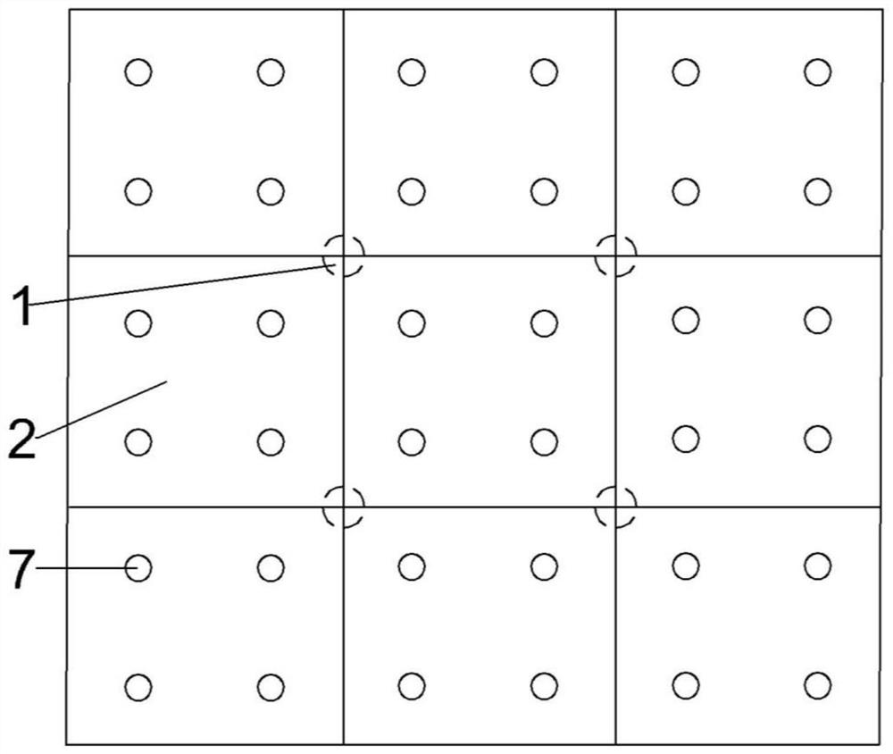
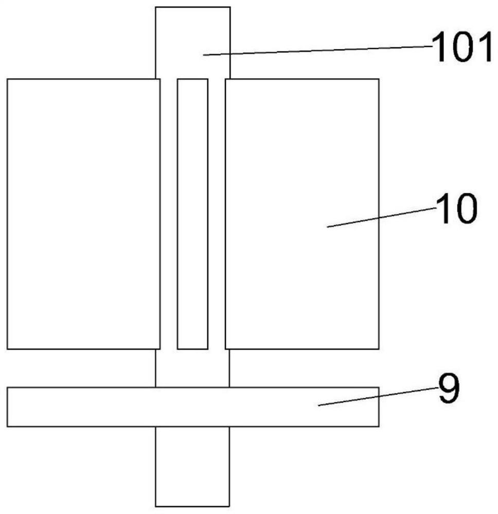
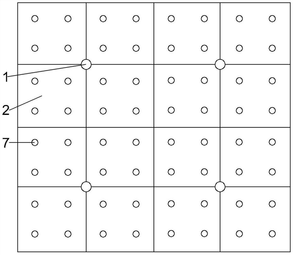
[0041] Refer Figure 1-4As shown, the present invention provides a lifting positioning device for assembling a cement concrete pave plate, including a plurality of positioning columns 1, support table 5, and the positioning column 1 and the support table 5 are respectively connected to the subgrade, and the concrete pave plate 2 is placed. At the outer circumferential direction of the positioning column 1, the outer circumferential direction of the positioning column 1 is provided with four positioning plates 10, and the four positioning plates 10 are vertically disposed, and several adjustment holes 7 are opened on the concrete floor panel 2, and the hole 7 is adjusted. Plug the guiding bracket 8, the concrete panel 2 is placed above a plurality of support tables 5.

[0042] First, the position of the positioning plate 10 is determined, the positioning plate 10 is the main reference point of the entire road construction; the positioning plate 10 can be positioned to locate the con...

Embodiment 2

[0045] Refer Figure 3-13 As shown, the positioning method of the present embodiment and the embodiment of the embodiment is only:

[0046] Further optimizing the scheme, further comprising several sealing strips 4, several sealing strips 4 cross-fixed each other, and the plurality of support tables 5 are disposed inside the sealing strip 4, the sealing strip 4, the support table 5 fixedly connected to the subgrade, sealing strip 4, respectively, sealing strip 4 The top surface of the support station is equal to the bottom surface of the concrete panel 2. After the sealing strip 4 is mainly after the construction of the concrete floor panel 2, the slurry remains below the concrete panel 2 in the grouting process, does not leak, after mud hardening, producing a good bonding effect.

[0047] Further optimization scheme, the positioning column 1 is disposed at the center of the sealing strip 4, and the positioning column 1 is fixedly connected to the intersection of the sealing strip ...

Embodiment 3

[0070] Refer Figure 4As shown, the positioning method of the present embodiment and the second embodiment of the second embodiment is only:

[0071] If the subgrade is the soil floor, first use the measuring instrument to determine the positioning point; steps in the second to fourth cement concrete, the positioning reference, the sealing strip 4 and the support table 5 are fixed by a steel bar (not shown) in the figure, and forming a steel bar network. Find the process and the grouting process as the example one.


PUM


Abstract

The invention provides a hoisting and positioning device and method for an assembly type cement concrete pavement panel, the hoisting and positioning device comprises a plurality of positioning columns and a supporting table, the positioning columns and the supporting table are connected to a roadbed, the concrete pavement panel is placed among the positioning columns, and four positioning plates are arranged on the outer sides of the positioning columns at equal intervals in the circumferential direction; the four positioning plates are vertically arranged, a plurality of adjusting holes are formed in the concrete pavement plate, guide supports are inserted into the adjusting holes, and the concrete pavement plate is placed above the supporting tables. According to the hoisting and positioning device, the construction process of the fabricated cement concrete pavement slabs can be rapidly achieved, the position of each cement concrete pavement slab can be rapidly positioned with high precision, the uneven positions of the cement concrete pavement slabs can be adjusted, construction is flexible, the construction difficulty is reduced, and the construction progress can be improved.

Description

Technical field [0001] The invention belongs to the field of road construction position, and more particularly to a lifting positioning apparatus and method for assembling a cement concrete panel. Background technique [0002] As the city's continuous expansion and the increase in road mileage, the speed of the road is accelerated. On construction sites such as airplane runway, house construction, subway construction, underground pipeline, underground people's sidewalk construction, etc., due to the need to transport the land, concrete, concrete, brick, and templates, etc., usually Temporary roads need to be laid on the site. Traditional road expansion projects need to cast concrete on site. Most of my country's construction project is mostly used for one-time current-casting concrete. The space occupied by the site is large, the construction period is long, and the weather is serious, and the interference of traffic is very serious. People's travel have a relatively large impact...

Claims


Application Information

Patent Timeline
IPC IPC(8): E01C19/52
CPCE01C19/52Y02A30/60
Inventor 李思李田波谢晋德权磊李立辉张盼盼何哲
Owner RES INST OF HIGHWAY MINIST OF TRANSPORT
Learn More