
Copper pre-plating method, copper plating method and copper plating device for superconducting strip

A technology of superconducting strip and pre-copper plating, which is applied in electrolysis process, electrolysis components, etc., can solve the problems that cannot solve the performance of the strip, and the bone structure of the strip affects the winding of the strip, so as to provide electroplating efficiency, power line Uniformity and non-concentration, the effect of improving processing efficiency

Pending Publication Date: 2021-07-09
SHANGHAI SUPERCONDUCTOR TECH CO LTD
View PDF2 Cites 5 Cited by
  • Summary
  • Abstract
  • Description
  • Claims
  • Application Information

AI Technical Summary

Problems solved by technology

If the surface of the superconducting strip is plated with sandy copper in the sand surface copper solution, the bone structure of the strip will affect the winding of the strip.
[0010] Patent document CN108342757B discloses a method for electroplating copper to prepare a high-temperature superconducting strip protective layer, which includes the following steps: step 1, preparing a copper protective layer on the high-temperature superconducting strip by using a copper electroplating process; step 2, preparing a copper protective layer on the back of the superconducting layer The baseband is electroplated with copper, but this design still cannot solve the problem that the liquid contacts the strip through the holes on the silver-plated surface and affects the performance of the strip

Method used


Image

  • Copper pre-plating method, copper plating method and copper plating device for superconducting strip
  • Copper pre-plating method, copper plating method and copper plating device for superconducting strip
  • Copper pre-plating method, copper plating method and copper plating device for superconducting strip

Examples


Embodiment 1

[0074] The invention provides a method for pre-plating copper on superconducting strips, which is not only suitable for electroplating of narrow strips, such as strips with a width of 1 mm to 3 mm, but also suitable for wide strips, such as processed ones with a width greater than 3 mm. Strip material 9, can reach the effect in the present invention by adopting pre-plating, superconducting strip material pre-copper plating method is to adopt the first electric current to carry out pre-copper-plating treatment to processed strip material 9, wherein, described pre-copper-plating treatment Pre-plating additives that allow working at the current density of the first current are added to the copper pre-plating solution used, and the current density used by the preset current is 6-20A / dm 2 , the weight composition of described pre-plating copper electroplating solution is:

[0075] 200-240 parts of copper sulfate;

[0076] 50-70 parts of sulfuric acid;

[0077] Chloride ion 0.08~0...

Embodiment 2

[0093] This embodiment is a preferred example of Embodiment 1.

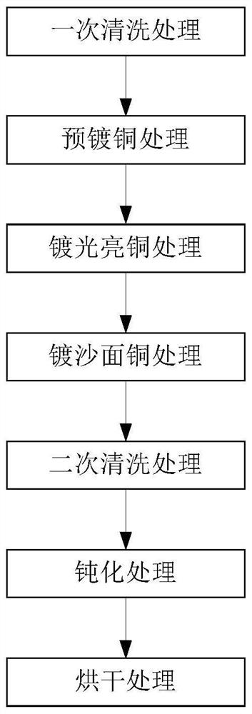
[0094] In this embodiment, the superconducting strip is first cleaned with pure water, and then the superconducting strip is subjected to the first current pre-copper plating treatment, the third current electroplating bright copper treatment, and the second current electroplating sand copper layer treatment, and then proceeds again. Cleaning with pure water, passivation treatment, drying, and drying to complete the copper plating operation of the superconducting strip.

[0095] After the superconducting strip is cleaned with ultrasonic pure water, use a current density of 10A / dm 2 Rapid pre-plating copper layer with high current, so that copper can quickly cover the surface of double-sided silver-plated superconducting bare tape, and then use 2A / dm after pre-plating 2 The current density is used to electroplate the bright copper layer to make the thickness in the middle and the surface smooth, and then use 6A / d...

Embodiment 3

[0098] This embodiment is another preferred example of Embodiment 1.

[0099] In this embodiment, the superconducting tape is carried out through a linear arrangement. After coming out of the discharge end of the discharge mechanism 1, it will first pass through a section of 60-180 cm adjustable ultrasonic pure water cleaning tank to clean the surface impurities. The belt will pass through 2~8 copper plating pre-plating tanks to quickly plate the copper cladding layer on the surface of the silver layer of the strip. The pre-plating copper plating solution used for the pre-plating is added to allow 6~20A / dm 2 The pre-plating acid copper additive for current density work will pass through 6 to 36 bright copper plating tanks to increase the thickness of the relatively uniform copper layer. Ability of bright copper copper additives, use 0.5 ~ 3.5A / dm 2 The current density can obtain the ideal intermediate copper layer, and the tape will pass through 2 to 8 sand surface copper gro...


PUM

PropertyMeasurementUnit
Roughnessaaaaaaaaaa

Abstract

The invention provides a copper pre-plating method, a copper plating method and a copper plating device for a superconducting strip. The copper plating device for the superconducting strip comprises a discharging mechanism, a first cleaning mechanism, a copper pre-plating mechanism, a bright copper plating mechanism, a sand surface copper plating mechanism, a second cleaning mechanism, a passivation mechanism, a drying mechanism and a collecting mechanism. The discharging mechanism is used for unwinding the machined strip, the machined strip sequentially passes through the first cleaning mechanism, the copper pre-plating mechanism, the bright copper plating mechanism, the sand surface copper plating mechanism, the second cleaning mechanism, the passivation mechanism and the drying mechanism during machined and is wound on the collecting mechanism, the copper pre-plating mechanism adopts first current electroplating treatment, the bright copper plating mechanism adopts third current electroplating treatment, and the sand surface copper plating mechanism adopts second current electroplating treatment. By adopting the design of copper pre-plating, copper plating and the like, the problem that a superconducting layer is corroded by liquid is solved, and meanwhile, the electroplated superconducting strip is good in quality and high in electroplating efficiency.

Description

technical field [0001] The invention relates to the technical field of superconducting materials, in particular to a method for pre-plating copper on a superconducting strip, a copper-plating method and a copper-plating device. Background technique [0002] Since the first discovery of superconductivity in the laboratory by Professor Camerin Onners of Leiden University in the Netherlands in 1911, superconducting materials and their applications have been one of the most active frontier research fields in contemporary science and technology. In the past ten years, the research on superconducting power devices based on superconductivity has developed rapidly. In superconducting energy storage, superconducting motors, superconducting cables, superconducting current limiters, superconducting transformers, superconducting magnetic levitation, Remarkable achievements have been made in fields such as nuclear magnetic resonance. [0003] High-temperature superconducting materials a...

Claims


Application Information

Patent Timeline
IPC IPC(8): C25D3/38C25D5/10C25D5/18C25D5/34C25D5/48C25D7/06C25D17/00
CPCC25D3/38C25D5/10C25D5/18C25D17/00C25D7/0614
Inventor 朱佳敏张超虞兴洲赵大允陈思侃吴蔚赵跃丁逸珺
Owner SHANGHAI SUPERCONDUCTOR TECH CO LTD
Learn More