Device for cutting round glass

A circular and glass technology, applied in glass cutting devices, glass manufacturing equipment, manufacturing tools, etc., can solve the problems of insufficient cutting precision of glass plates and difficulties in cutting circular glass plates, etc.

Pending Publication Date: 2021-07-06
刘剑锋
View PDF0 Cites 2 Cited by
  • Summary
  • Abstract
  • Description
  • Claims
  • Application Information

AI Technical Summary

Problems solved by technology

[0005] In order to overcome the shortcomings of the existing technology that the cutting precision of glass plates is not high enough and it is relatively difficult in the process of cutting circular glass plates, the technical problem is: to provide an automatic cutting with high precision and reduce the loss of material due to improper cutting. wasteful device for cutting round glass

Method used


Image

  • Device for cutting round glass
  • Device for cutting round glass
  • Device for cutting round glass

Examples


Embodiment 1

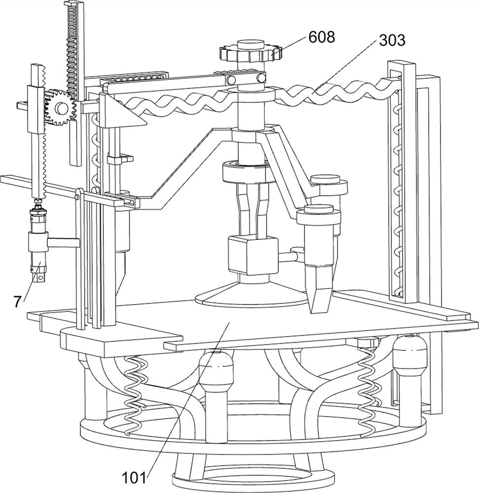
[0027] A device for cutting round glass such as figure 1 and figure 2 As shown, it includes an annular base 1, a glass plate 101, a placement assembly 2, a guide assembly 3 and a cutting assembly 4. The top of the annular base 1 is provided with a placement assembly 2, and the top of the placement assembly 2 is placed with a glass plate 101. Guide assemblies 3 are provided, and cutting assemblies 4 are arranged between the guide assemblies 3 .

[0028] When people need to cut the glass plate 101 into a circle, this device can be used. First, the glass plate 101 is placed on the placement assembly 2, and the guide assembly 3 is manually pressed, and the guide assembly 3 drives the cutting assembly 4 to move downward, thereby When the cutting assembly 4 is rotated, the glass plate 101 is cut in a circle. After cutting, put on gloves and use a tool to gently knock the excess glass plate 101 downwards. The excess glass will fall, and people can get a circle. shaped glass plate ...

Embodiment 2

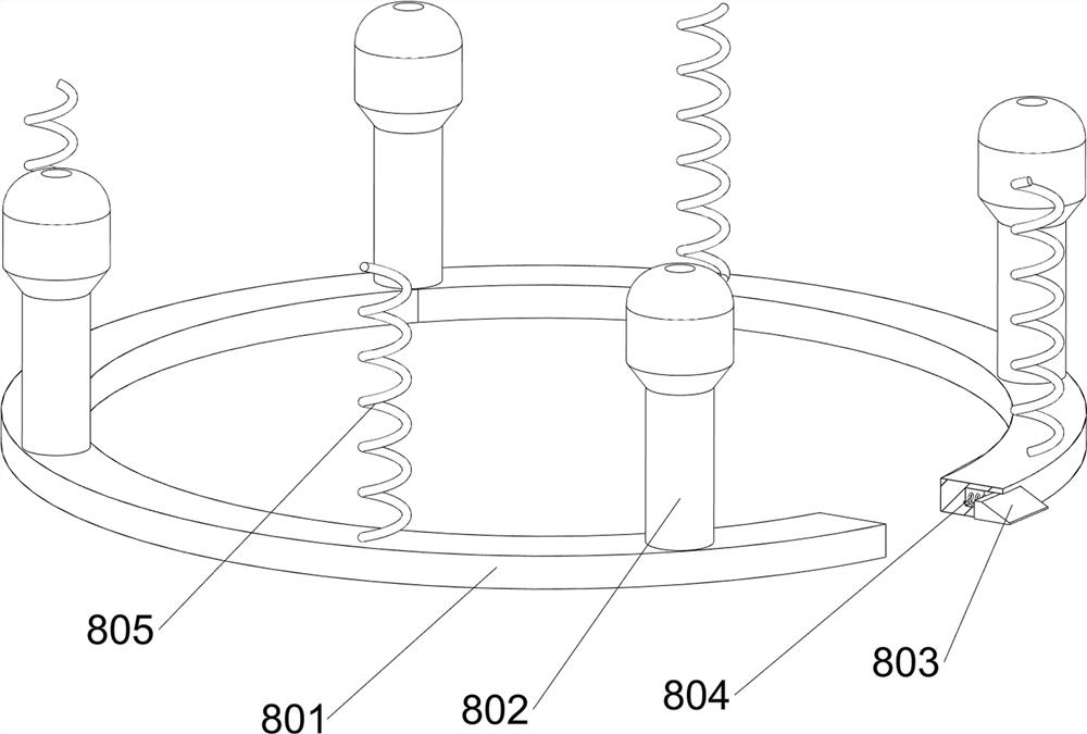
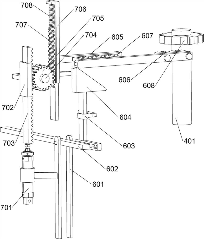
[0036]On the basis of Example 1, such as image 3 , Figure 4 , Figure 5 and Figure 6 As shown, a pressing assembly 5 is also included. The pressing assembly 5 includes a bearing 501, a suction cup 502, a buckle 503, a second spring 504 and a handle 505. The bottom of the first rotating shaft 401 is provided with a bearing 501, and the bottom of the bearing 501 is provided with a Fixed block, the sliding type in the fixed block is provided with a handle 505, the bottom of the fixed block is connected with a suction cup 502, the suction cup 502 cooperates with the handle 505, the sliding type in the rear side of the fixed block is provided with a buckle 503, and a buckle 503 is provided between the buckle 503 and the fixed block. There is a second spring 504 , and the buckle 503 cooperates with the handle 505 .

[0037] When the first rotating shaft 401 moves downward, it drives the bearing 501 to move downward, so that the bearing 501 drives the suction cup 502 to move do...


PUM


Abstract

The invention relates to a cutting device, and especially relates to a device for cutting round glass. The device for cutting the round glass aims at achieving the technical purposes that the automatic cutting precision is high, and material waste caused by improper cutting is reduced. According to the technical scheme, the device for cutting the round glass comprises an annular base, a glass plate, a placing assembly, guide assemblies and a cutting assembly; and the placing assembly is arranged at the top of the annular base, the glass plate is placed at the top of the placing assembly, guide assemblies are arranged on the placing assembly, and the cutting assembly is arranged between the guide assemblies. After the glass plate is fixed, a glass cutter and a special-shaped frame which do not generate strenuous vibration are used for driving the glass plate to rotate to determine a circle, then the glass plate is rotated again for cutting, and finally a rubber hammer is used for lightly knocking the redundant part of the glass plate, so that the effect of reducing material waste caused by improper cutting is achieved.

Description

technical field [0001] The invention relates to a cutting device, in particular to a device for cutting circular glass. Background technique [0002] Glass, also known as glass, is a hard and brittle transparent object without a certain melting point. Generally, it is mixed with quartz sand, limestone and soda ash, and then melted in a high-temperature device and slowly formed. , made after waiting for cooling. [0003] However, when people need to cut it into a circular glass plate, they need to manually draw a circle and then cut it. However, the accuracy of the manual circle is not high enough. If it is not accurate enough, the cut out will not meet the production requirements and will be broken. Material waste is caused, and the glass plate is in contact with the cutting tool during cutting, and the frequent vibration and cutting of the cutting tool may easily cause the glass plate to break during the cutting process, causing people to be injured. [0004] In view of t...

Claims


Application Information

Patent Timeline
IPC IPC(8): C03B33/04
CPCC03B33/04
Inventor 刘剑锋
Owner 刘剑锋
Why Eureka
Try Eureka