Internal combustion engine piston monitoring system achieving induction power supply

An inductive power supply and monitoring system technology, applied in the direction of electrical components, circuit devices, mechanical equipment, etc., can solve the problems of signal shielding, lead wire winding, large power consumption, etc., achieve reliable working performance, improve collection efficiency, and improve reliability Effect

Active Publication Date: 2021-07-02
KUNMING UNIV OF SCI & TECH
View PDF4 Cites 0 Cited by
  • Summary
  • Abstract
  • Description
  • Claims
  • Application Information

AI Technical Summary

Problems solved by technology

[0006] In order to solve the problems existing in the existing monitoring methods such as lead wire winding, high device power consumption, signal shielding, etc., the present invention uses wireless communication to complete the data inside the internal combustion engine monitoring and transmission, reducing the steps of modification and wiring of the device under test, and reducing the difficulty of the experiment; for the problem of low working time and high power consumption of the experimental system, the present invention introduces the induction power supply method, and cuts the magnetic induction through the swing of the connecting rod. The system is powered by the line, which prolongs the working time of the system, makes full use of energy, and solves the defect of system power supply

Method used


Image

  • Internal combustion engine piston monitoring system achieving induction power supply
  • Internal combustion engine piston monitoring system achieving induction power supply
  • Internal combustion engine piston monitoring system achieving induction power supply

Examples


Embodiment 1

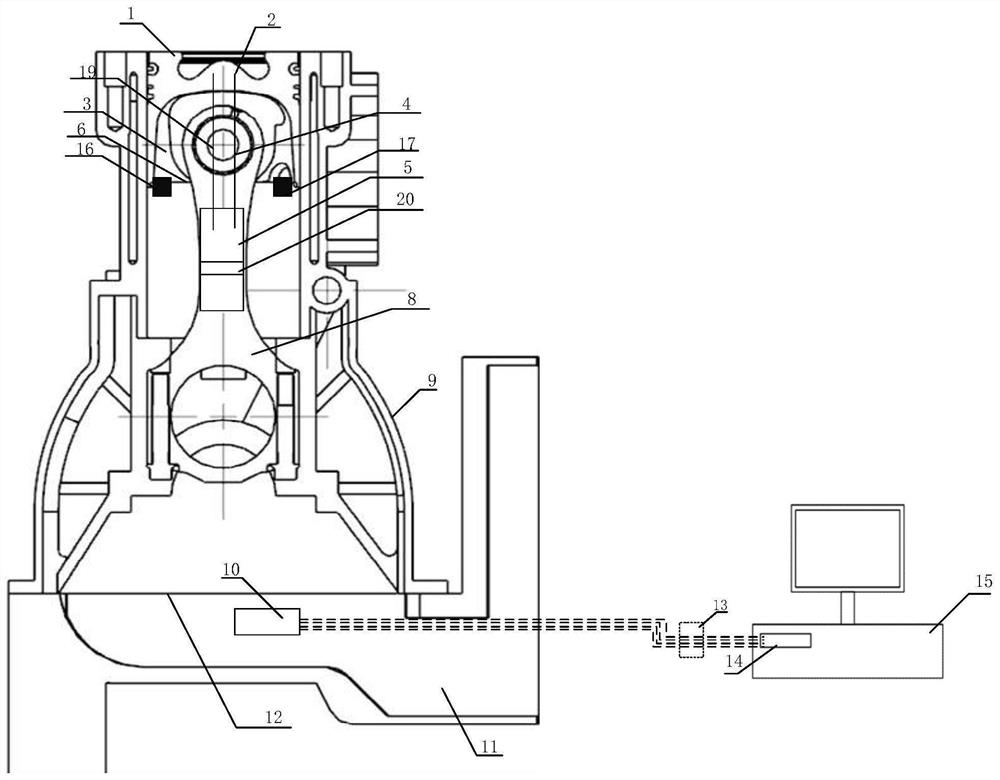
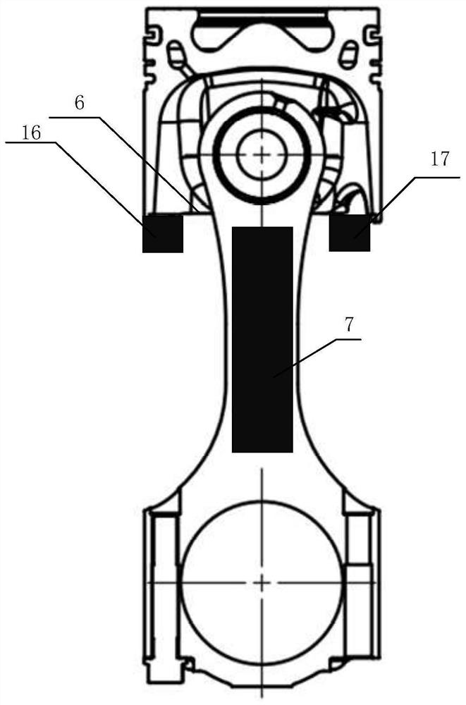
[0042] An inductively powered internal combustion engine piston monitoring system such as figure 1 , 2 , 3, 4, including thermocouple 4, controller 5, power supply 7, wireless transmitter-USB converter 10, data cable 13, USB serial port 14, computer 15, permanent magnet Ⅰ 16, permanent magnet Ⅱ 17, coil 18, strain gauge 19. Triaxial acceleration sensor 20, power supply box 21;

[0043] Thermocouple 4, strain gauge 19, triaxial acceleration sensor 20 are respectively connected with controller 5, and controller 5 is connected with power supply 7, and power supply 7 is a rechargeable storage battery, and power supply 7 is placed in power supply box 21, and power supply box 21 is a ceramic insulation Made of thermal material, the coil 18 is wound outside the power supply box 21, and the charging end of the power supply 7 is connected to the coil 18;

[0044] The controller 5 is wirelessly connected to the wireless transmitter-USB converter 10, the wireless transmitter-USB conver...

Embodiment 2

[0057] An inductively powered internal combustion engine piston monitoring system such as Figure 7 , 8 , 9, 10, 11, 12, 13, on the basis of embodiment 1, also includes vacuum heat insulation hose 22, fixed frame 23, antenna 24, radome 25, damping material 26, damping spring 27, power cord 28. Ceramic heat insulation box 29, data line fixing piece 30, data line hole 31, airgel 32, sensor line fixing piece 33, sensor line hole 34, sensor line buckle 35, data line buckle 36;

[0058] The vacuum heat insulation hose 22 is bonded to the connecting rod 8. The vacuum heat insulation hose 22 is a vacuum heat insulation hose produced by Chengdu Huohuo Cryogenic Equipment Co., Ltd., which is made of double-layer stainless steel metal hose, and heat insulation material is added in the interlayer Such as asbestos, etc., the fixed frame 23 is placed in the vacuum insulation hose 22, the fixed frame 23 includes two triangular blocks, the controller 5 is placed in the middle of the longest...


PUM


Abstract

The invention discloses an internal combustion engine piston monitoring system achieving induction power supply. The internal combustion engine piston monitoring system comprises a sensor, a controller, a power source, a wireless transmitter-USB converter, a data line, a USB serial port and a computer. The internal combustion engine piston monitoring system is high in universality, low in cost and high in operability, transmission of different kinds of functional data of a piston is completed in a wireless communication manner, power is permanently supplied to the system in a magnetic induction line cutting manner, the defects of a traditional monitoring method are overcome, observability of monitoring data and reliability of an internal combustion engine piston testing system are improved, and the experiment difficulty is reduced.

Description

technical field [0001] The invention relates to the technical field of electronic monitoring of internal combustion engines, in particular to an inductively powered internal combustion engine piston monitoring system. Background technique [0002] As a stable and reliable power source, the internal combustion engine is widely used in vehicles and ships; the piston of the internal combustion engine is the core of the power output part (module) of the internal combustion engine, and it is also one of the most demanding parts of the internal combustion engine. In the working environment, it not only needs to withstand Large external pressure, mechanical load, and huge heat load due to the heat transfer of high-temperature gas will cause the mechanical performance of the internal combustion engine piston to decline, and the top is prone to ablation and cracking, thereby reducing the service life of the engine. Therefore, the monitoring of different performance parameters of pist...

Claims


Application Information

Patent Timeline
Patent Type & Authority Applications(China)
IPC IPC(8): F02B77/08H02J50/00
CPCF02B77/08H02J50/00
Inventor 邓晰文姜波雷基林申立忠白永瑞高升王金昆颜绍祥刘弘灿
Owner KUNMING UNIV OF SCI & TECH
Why Eureka
Try Eureka