
Multifunctional protection device for battery system

A protection device and battery system technology, which is applied in the direction of electrical equipment, battery/battery traction, electric vehicles, etc., can solve problems such as unfavorable battery system protection, positive and negative high-voltage charging, waterproof performance failure, etc., to achieve a benefit to the overall Layout, reduction of openings, and cost savings

Pending Publication Date: 2021-07-02
SHANDONG YIXING ELECTRIC AUTO CO LTD
View PDF7 Cites 0 Cited by
  • Summary
  • Abstract
  • Description
  • Claims
  • Application Information

AI Technical Summary

Problems solved by technology

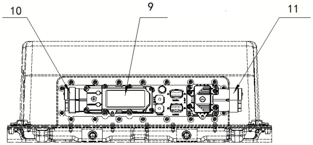
[0005] 1. The protection level of the power battery box is required to reach IP67 and above, and the installation of the existing manual maintenance switch 9 on the box increases the risk of failure of the waterproof performance;
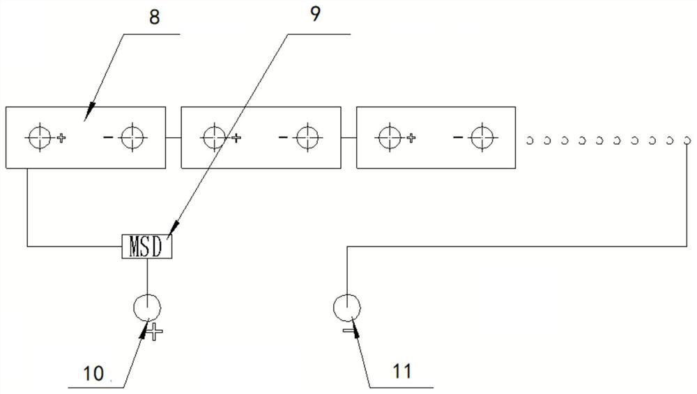
[0006] 2. In the power battery system, the connection point is a potential failure point that generates problems such as heat generation and virtual connection. This solution adds 2*(N-1) potential failure points;
[0007] 3. In the battery system of the whole vehicle, only the existing manual maintenance switch 9 in the middle box is equipped with a fuse, and the other existing manual maintenance switches 9 without fuses are installed in the battery box, which not only increases the risk but also increases the production cost;
[0008] 4. The existing protection device only meets the national standard. The existing manual maintenance switch 9 and fuse are installed. There is still a risk of live work when the maintenance personnel manually plug in and out. When the fuse in the existing manual maintenance switch 9 fails to fuse , the positive and negative electrodes still have risks such as high voltage charging, short circuit, thermal runaway, etc., which is not conducive to the protection of the battery system

Method used


Image

  • Multifunctional protection device for battery system
  • Multifunctional protection device for battery system
  • Multifunctional protection device for battery system

Examples


Embodiment Construction

[0038] An exemplary embodiment of the present disclosure will be described in more detail below with reference to the accompanying drawings. Although the exemplary embodiments of the present disclosure are shown in the drawings, it is understood that the present disclosure can be implemented in various forms and should not be restricted herein. Instead, it is provided to provide more thoroughly understood the present disclosure, and can communicate the scope of the disclosure to those skilled in the art.

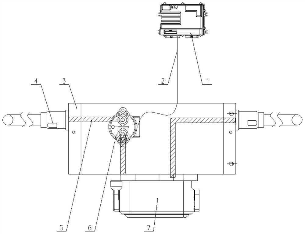
[0039] Such as Figure 3 ~ 4 As shown, the present embodiment provides a battery system multifunctional protection device 13, and the protection device 13 includes a high voltage connector 4, a high voltage contactor 6, a manual maintenance switch 7, and a conductive strip 5, and high voltage connector 4 are provided with two , The high voltage connector 4, the high voltage contactor 6, the manual maintenance switch 7 and the high voltage connector 4 are connected in sequence, an...


PUM


Abstract

The invention discloses a multifunctional protection device for a battery system, which comprises two high-voltage connectors for connecting batteries, and the high-voltage connector, a high-voltage contactor, a manual maintenance switch and the high-voltage connector are sequentially connected through conductive bands; the high-voltage contactor can switch on or off states according to a received control signal; the manual maintenance switch can be switched on or off by shifting the manual maintenance switch. The protection device is connected in series in the battery system to save the total cost of the battery system; the protection device realizes dual protection by using the high-voltage contactor and the manual maintenance switch, reduces the safety risk when the whole vehicle breaks down, ensures the personnel safety, effectively cuts off the battery system in real time according to the control strategy of the battery system, and has a better protection effect on the battery system of a passenger car. The protection device has the advantages of being flexible in installation and convenient to maintain, and overall arrangement of the whole vehicle battery system is better facilitated.

Description

Technical field [0001] The present invention relates to the technical field of electric vehicle battery systems, particularly refers to a multi-functional protection device for a battery system. Background technique [0002] The safety protection of the power battery system of electric vehicles is an important indicator of electric passenger cars. The power battery system of electric passengers and passenger cars are different. The battery of the passenger car is generally installed in the chassis, and the installation of electric passets There are more and dispersion. The battery system of the electric vehicle is generally consisting of three and more than 3 battery tanks. Some electric passenger cars that require high power, even more than ten battery boxes, and the voltage is very high, the storage energy is very large, and once shorted or malfunction, The damage caused is very large, so "GB38032-2020 Electric Passenger Cars Safety Requirements" is that "the chargeable energy ...

Claims


Application Information

Patent Timeline
Patent Type & Authority Applications(China)
IPC IPC(8): B60L3/00B60L50/60
CPCB60L3/00B60L50/60Y02T10/70
Inventor 郭兴龙王恩前林伟林超范宗武王波
Owner SHANDONG YIXING ELECTRIC AUTO CO LTD
Learn More