
Milling cutter machining device and using method thereof

A processing device and milling cutter technology, applied in heating devices, milling cutters, grinding drive devices, etc., can solve the problems of operator injury, debris splashing, affecting the normal operation of the device, etc., to avoid injury and increase friction. , Improve the effect of grinding effect

Active Publication Date: 2021-07-02
株洲耀辉光机电研究开发有限公司
View PDF5 Cites 0 Cited by
  • Summary
  • Abstract
  • Description
  • Claims
  • Application Information

AI Technical Summary

Problems solved by technology

[0003]In order to make the produced parts meet the precision requirements, the tool needs to be ground, but the debris generated by the current tool grinding device splashes around, which is more likely to cause injury to the operator In addition, there is no special heat dissipation device on the processing equipment, and a large amount of heat will be generated during the grinding operation of the grinding equipment and the grinding parts, and the overheating environment will directly affect the normal operation of the device

Method used


Image

  • Milling cutter machining device and using method thereof
  • Milling cutter machining device and using method thereof
  • Milling cutter machining device and using method thereof

Examples


Embodiment 1

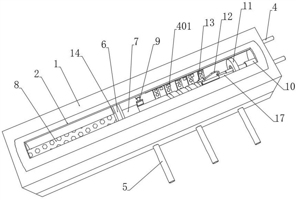
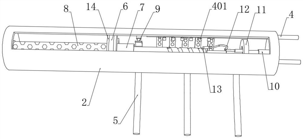
[0045] see Figure 1-3 , a milling cutter processing device, including an embedded seat 1 and a processing roller 2 fixedly embedded in the embedded seat 1, a processing cavity is opened inside the processing roller 2, and an arc is installed on the top of the processing roller 2 to rotate. shaped sealing cover 201, the inside of the processing chamber is embedded with a partition 6, the partition 6 divides the inside of the processing chamber into a drying chamber and a cooling and grinding chamber, the upper and lower ends of the partition 6 are all embedded with a semiconductor refrigeration chip 14, The middle part of the board 6 is provided with a positioning column 7, one end of the positioning column 7 penetrates into the drying chamber and is fixedly connected with a drying column 8, and the other end of the drying column 8 is against the inner wall of the drying chamber. The left and right sides of 7 are provided with fixtures 9 for clamping the milling cutter;

[00...


PUM


Abstract

The invention discloses a milling cutter machining device and a using method thereof, and belongs to the technical field of milling cutter machining. A pair of semiconductor chilling plates is embedded in a partition plate of a machining roller, the semiconductor chilling plates are used for cooling the interior of a polishing chamber, and in the milling cutter polishing process, continuously supplied cold air is used in cooperation with water mist, on one hand, the overall temperature of the polishing chamber is lowered, on the other hand, water mist can locally form ice chips under the condition of further temperature lowering, the ice chips are sprayed to the surface of the milling cutter, the friction force between a milling cutter polishing body and the milling cutter is increased, and the polishing effect is improved; and meanwhile, a heat conductor arranged on the inner wall of a water cooling drying chamber can adsorb space heat, the heat is dissipated under driving of water flow, a blow-off pipe is used in cooperation with a suction pump to discharge waste water, heat in the polishing chamber can be sucked out, the polished milling cutter is pushed into a drying column, the milling cutter is dried by heat generated at the other ends of the semiconductor chilling plates, and integration of polishing, cooling and drying of the milling cutter is effectively achieved.

Description

technical field [0001] The invention relates to the technical field of milling cutter processing, and more specifically, relates to a milling cutter processing device and a method for using the same. Background technique [0002] Milling cutter is a kind of cutting tool for finishing. It is widely used in wood and steel processing industries. In the process of mechanical processing, the use of cutting tools is inseparable. The long-term use of cutting tools will cause wear and tear, and worn cutting tools will affect the processing of parts. Accuracy, among them, end mills are used to process grooves and stepped surfaces, etc., and the teeth are on the circumference and end faces. [0003] In order to make the produced parts meet the precision requirements, the tool needs to be ground, but the debris generated by the current tool grinding device splashes around, which is easy to cause injury to the operator; in addition, there is no special heat dissipation device on the pro...

Claims


Application Information

Patent Timeline
Patent Type & Authority Applications(China)
IPC IPC(8): B24B3/02B24B55/02B24B55/06B24B41/00B24B41/06B24B47/06B25J11/00F26B23/00F25B21/02
CPCB24B3/02B24B55/02B24B55/06B24B41/005B24B41/06B24B47/06B25J11/0065F26B23/00F25B21/02
Inventor 胡欢
Owner 株洲耀辉光机电研究开发有限公司
Learn More