
Multi-beam reflecting surface antenna taking circularly-polarized high-gain resonant antenna as feed source

A resonant antenna, high-gain technology, applied in the direction of resonant antenna, antenna, antenna array, etc., can solve problems such as unfavorable structure, increase feed source profile height, increase structural complexity, etc., to achieve easy power feeding, good engineering application prospects, highly directional effect

Active Publication Date: 2021-06-25
SOUTHEAST UNIV
View PDF5 Cites 1 Cited by
  • Summary
  • Abstract
  • Description
  • Claims
  • Application Information

AI Technical Summary

Problems solved by technology

At present, the multi-beam reflector feed mainly uses an additional circular polarizer inserted in the waveguide to realize the conversion from linear polarization to circular polarization, which increases the complexity of the structure and increases the profile height of the feed. Not conducive to the simplification of the structure

Method used


Image

  • Multi-beam reflecting surface antenna taking circularly-polarized high-gain resonant antenna as feed source
  • Multi-beam reflecting surface antenna taking circularly-polarized high-gain resonant antenna as feed source
  • Multi-beam reflecting surface antenna taking circularly-polarized high-gain resonant antenna as feed source

Examples


Embodiment Construction

[0024] The structure and performance of the present invention will be further described below in conjunction with the accompanying drawings. It should be understood that these embodiments are only used to illustrate the present invention and are not intended to limit the scope of the present invention. After reading the present invention, those skilled in the art all fall into the appended claims of the present application to the amendments of various equivalent forms of the present invention limited range.

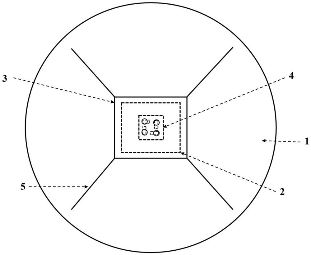
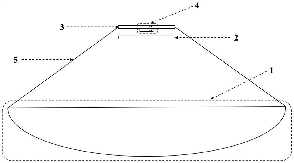
[0025] Such as figure 1 As shown, the multi-beam reflector antenna based on a circularly polarized high-gain resonant antenna as a feed source includes a rotating parabolic reflector 1, and a circularly polarized high-gain resonant antenna is placed at the focus of the rotating parabolic reflector and used with a bracket 5 fixed.

[0026] Such as figure 1 As shown, the multi-beam reflector antenna based on the circularly polarized high-gain resonant antenna as the feed...


PUM

PropertyMeasurementUnit
lengthaaaaaaaaaa
lengthaaaaaaaaaa
widthaaaaaaaaaa

Abstract

The invention discloses a multi-beam reflecting surface antenna taking a high-gain circularly-polarized resonant cavity antenna as a feed source, which comprises a rotating parabolic reflecting surface (1), wherein the circularly-polarized high-gain resonant cavity antenna is placed on a focal plane of the rotating parabolic reflecting surface as the feed source and is fixed by a bracket (5). The circularly-polarized high-gain resonant antenna serving as the feed source is composed of a linear polarization-to-circular polarization partially reflecting surface (2), a metal floor (3) and a linear polarization patch array (4). According to the invention, the conversion from linear polarization to circular polarization is realized by utilizing the partially reflecting surface in the resonant cavity antenna, meanwhile, relatively high gain is realized, and the circularly- polarized antenna is arranged on the focal plane of the reflecting paraboloid as a feed source, so that a plurality of wave beams are radiated on the aperture of the reflecting surface. Compared with a traditional multi-beam reflecting surface antenna with multiple horns as feed sources, the multi-beam reflecting surface antenna is simple in feed source structure and more compact in arrangement, and can effectively overcomethe problem of beam coverage.

Description

technical field [0001] The invention belongs to the technical field of microwave devices, and relates to a multi-beam reflector antenna based on a circularly polarized high-gain resonant antenna as a feed source. Background technique [0002] The increasing bandwidth demand of modern communications for satellite broadband communication services has driven substantial interest and investment in high-throughput satellite technologies. Most satellites today implement multi-beam technology to reuse frequency bands or polarizations within the desired coverage area. Using multiple feed sources located on the focal plane to irradiate the reflector and multi-beam reflector antenna to generate multiple beams is an important mechanism of multi-beam forming at present. However, this method has higher requirements on the feed source. Because in practical applications, the beam overlap area will have a decrease in gain, which will cause uneven beam coverage and affect the performance o...

Claims


Application Information

Patent Timeline
Patent Type & Authority Applications(China)
IPC IPC(8): H01Q15/16H01Q1/48H01Q9/04H01Q21/00H01Q21/06H01Q25/00
CPCH01Q15/16H01Q1/48H01Q21/065H01Q9/0407H01Q21/0006H01Q25/00
Inventor 刘震国应振楠陆卫兵
Owner SOUTHEAST UNIV
Learn More