
Method and device for accurately measuring temperature of SCR catalytic unit

A technology of SCR catalytic converter and catalytic unit, applied in the direction of muffler device, exhaust device, electronic control of exhaust gas treatment device, etc., can solve the problems of insufficient utilization of catalytic converter efficiency, inaccurate temperature measurement, etc., to reduce production costs and user cost, improve operating efficiency, and improve the effect of economy

Pending Publication Date: 2021-06-25
GUANGXI YUCHAI MASCH CO LTD
View PDF0 Cites 1 Cited by
  • Summary
  • Abstract
  • Description
  • Claims
  • Application Information

AI Technical Summary

Problems solved by technology

Then, the arithmetic mean value of the temperature sensor E before the SCR and the temperature sensor H after the SCR is used as the carrier temperature of the SCR catalyst. The temperature measurement in the case is not accurate, causing the efficiency of the catalytic converter to not be fully utilized

Method used


Image

  • Method and device for accurately measuring temperature of SCR catalytic unit
  • Method and device for accurately measuring temperature of SCR catalytic unit
  • Method and device for accurately measuring temperature of SCR catalytic unit

Examples


Embodiment Construction

[0034] The present invention will be further described below in conjunction with the specific embodiments in the accompanying drawings.

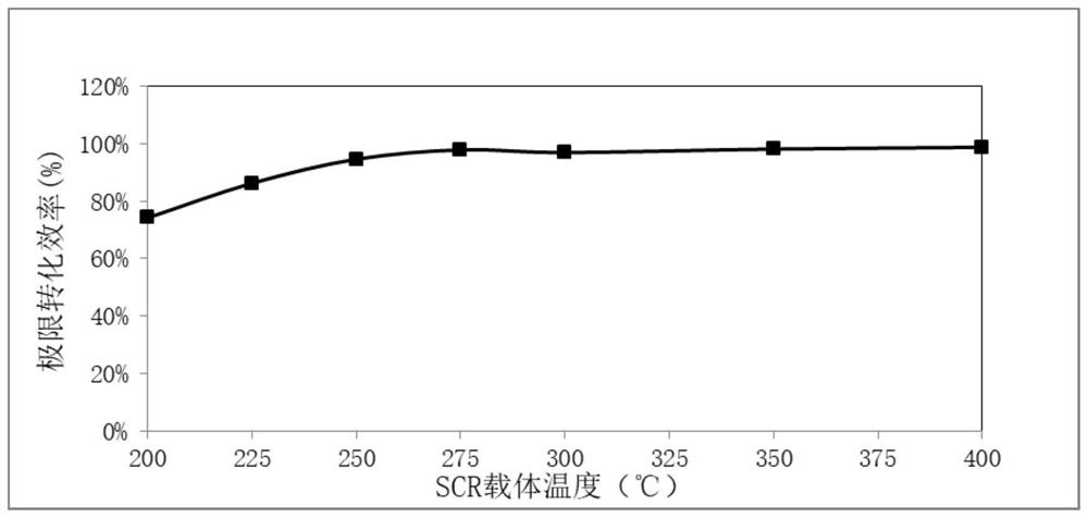
[0035] refer to image 3 , 4 , a method for accurately measuring the temperature of an SCR catalytic unit comprising:

[0036] In the experimental environment, obtain the temperature T of the front end of the SCR catalytic unit 1; obtain the temperatures T1-Tn of n different positions on the periphery of the circumference of the middle part of the SCR catalytic unit 1; obtain the temperature Tn+1 of the central position of the central part of the SCR catalytic unit 1;

[0037] Adjust the working conditions of the engine according to the set temperature interval, so that the temperature T gradually rises from the first temperature to the second temperature, and run stably for the set time at each working point. After the set time is reached, record each working condition Points corresponding to T, T1~Tn, Tn+1, calculate the correction coeff...


PUM


Abstract

The invention discloses a method and device for accurately measuring the temperature of an SCR catalytic unit, and relates to the technical field of engine tail gas treatment. The technical problem that the temperature of the SCR catalytic unit is not accurately measured is solved. The method comprises the steps that in an experimental environment, the temperature T of the front end of the SCR catalytic unit is obtained; the temperatures T1 to Tn of n different positions of the periphery of the circumference of the middle of the SCR catalytic unit are obtained; the temperature Tn +1 of the center of the middle of the SCR catalytic unit is obtained; the working condition of an engine is adjusted according to a set temperature interval, the temperature T is gradually increased to the second temperature from the first temperature, the engine stably runs for set time at each working condition point, after the set time is up, the temperatures T1 to Tn and Tn + 1 corresponding to all the working condition points are recorded, and the correction coefficient lambda which is (T1 +, + Tn + Tn + 1) / (n + 1) T corresponding to all the working condition points is calculated; a correction curve is made according to the correction coefficient lambda corresponding to all the working condition points; and in actual work, the correction curve is inquired according to the actual temperature of the front end of the SCR catalytic unit, and the actual working temperature of the SCR catalytic unit is obtained.

Description

technical field [0001] The invention relates to the technical field of engine exhaust gas treatment, more specifically, it relates to a method and device for accurately measuring the temperature of an SCR catalytic unit. Background technique [0002] Diesel engines equipped with SCR (Selective Catalytic Reduction) system optimize CO, HC, PM and other emissions to within the limit value of regulations through internal purification technology, and use SCR system for NOx emissions exceeding the limit value of regulations The amount of urea matching the engine operating conditions is injected into the exhaust pipe through the control unit, and the ammonia and nitrogen oxides decomposed from urea undergo catalytic reduction reactions in the catalyst to finally generate harmless nitrogen (N2) and water (H2O ) to reduce NOx emissions, and finally achieve NOx emissions to meet the requirements of regulations. Its main chemical reaction mode is as follows: [0003] NO+NO2+2NH3->...

Claims


Application Information

Patent Timeline
Patent Type & Authority Applications(China)
IPC IPC(8): F01N3/28F01N13/00F01N11/00
CPCF01N3/28F01N13/008F01N11/002F01N2560/06Y02T10/40
Inventor 王晓辉肖刚李之华
Owner GUANGXI YUCHAI MASCH CO LTD
Learn More