Vascular intervention stent

A vascular and tubular technology, applied in the field of vascular interventional stents, can solve the problems of high difficulty and risk in intracranial surgery, high difficulty in assembly, and large filter mesh, so as to avoid the risk of intracranial hemorrhage, use it safely and reliably, and improve surgical procedures. effect of effect

Pending Publication Date: 2021-06-25
MICROPORT NEUROTECH SHANGHAI
View PDF12 Cites 0 Cited by
  • Summary
  • Abstract
  • Description
  • Claims
  • Application Information

AI Technical Summary

Problems solved by technology

Other intracranial vascular stents have no ability to filter emboli
Moreover, the existing intravascular filtering devices have the following problems and are not suitable for intracranial blood vessels:
[0004] 1. The mesh of the filter is large, the filtering capacity is insufficient, and the anchoring force is low, which cannot adapt to the intracranial blood vessels with faster blood flow and smaller emboli;
[0005] 2. The intracranial vascular access is tortuous and complicated, and interventional surgery is difficult. Sometimes a second pass of surgical instruments is required, but a fully enclosed filter device cannot meet this requirement;
[0006] 3. The filtering device and the anchoring device are independent of each other and need to be assembled through certain connection methods, while the size of the intracranial interventional device is extremely small, the assembly is difficult, and it will introduce the risk of assembly failure, and the size of the entire device is also relatively large;
[0007] 4. It needs to be recycled regularly, otherwise it may cause thrombus, but intracranial surgery is difficult and risky, so it is not suitable for multiple operations

Method used


Image

  • Vascular intervention stent
  • Vascular intervention stent
  • Vascular intervention stent

Examples


Embodiment 1

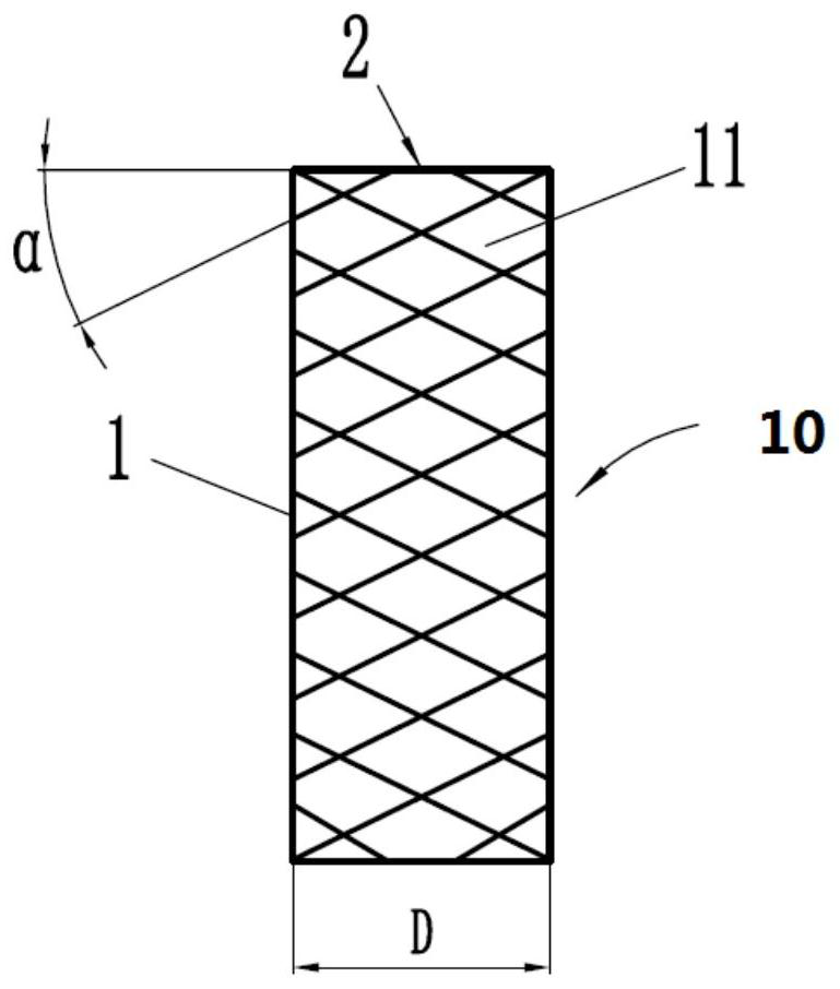
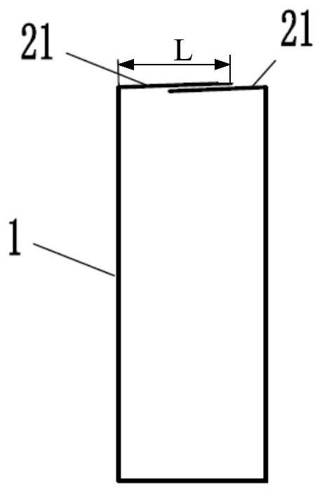
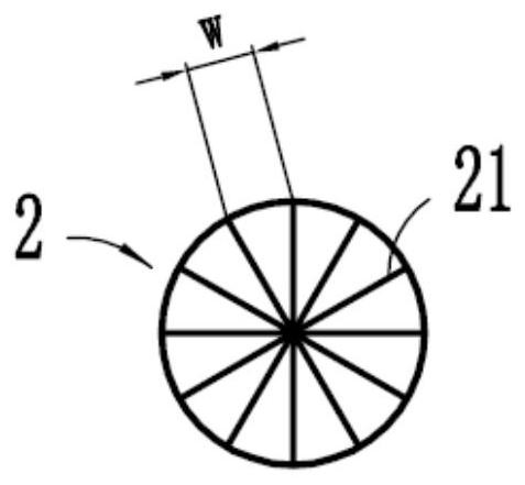
[0072] Figure 1a ~ Figure 1c They are respectively the front view, the axial sectional view and the top view of the vascular interventional stent provided by the first embodiment of the present invention.

[0073] Such as Figure 1a ~ Figure 1c As shown, the vascular intervention stent 10 includes a support structure 1 and a filter structure 2 . The support structure 1 is in the shape of a tube, which can be braided from braided wire, or cut by laser. The supporting structure 1 may be a self-expanding structure, or be passively expanded by an expandable balloon. Furthermore, the expanded diameter D of the support structure 1 is 3.0 mm to 4.5 mm, preferably 3.5 mm, which can be applied to relatively thin blood vessels, especially intracranial blood vessels.

[0074] The support structure 1 specifically includes a plurality of support rods 11, and the plurality of support rods 11 are distributed in a certain way to form a network-like support structure 1. However, the presen...

Embodiment 2

[0086] The structure of the vascular interventional stent provided in this embodiment is basically the same as that in Embodiment 1, and the following description will only focus on the different points, and the same parts will not be described in detail.

[0087] Figure 2a ~ Figure 2c They are the front view, axial sectional view and plan view of the vascular interventional stent provided by the second embodiment of the present invention, respectively.

[0088] Such as Figure 2a ~ Figure 2c As shown, the vascular intervention stent 20 includes a support structure 3 and a filter structure 4 . The expanded diameter D of the support structure 3 can be selected to be 5.5 mm to 6.0 mm, which can be applied to blood vessels with larger diameters. The support structure 3 includes several support rods 31, and the included angle α between the support rods 31 and the radial cross section of the support structure 3 is preferably 10°-15°, so as to provide good radial support for sten...

Embodiment 3

[0092] The structure of the vascular interventional stent provided in this embodiment is basically the same as that in Embodiment 1, and the following description will only focus on the different points, and the same parts will not be described in detail.

[0093] Figure 3a ~ Figure 3c They are the front view, axial sectional view and top view of the vascular interventional stent provided by the third embodiment of the present invention, respectively.

[0094] Such as Figure 3a ~ Figure 3c As shown, the vascular intervention stent 30 includes a support structure 5 and a filter structure 6 . The expanded diameter D of the support structure 5 can be selected to be 4.5 mm to 5.5 mm, which can be applied to blood vessels with medium diameters. The support structure 5 includes several support rods 51, and the included angle α between the support rods 51 and the radial cross-section of the support structure 5 is preferably 20°-25°, so as to provide good radial support for stents...


PUM


Abstract

The invention relates to an endovascular intervention stent, which is mainly applied to filtration of intracranial blood vessels, can achieve the purpose of long-term filtration of emboli in the intracranial blood vessels, and is also convenient for other interventional medical instruments to realize interventional therapy of other parts of the blood vessels through the stent, so that the disease treatment effect is improved. The vascular intervention stent comprises a supporting structure and a filtering structure, the supporting structure is tubular, the filtering structure is of a net-shaped structure and is connected with the supporting structure, the filtering structure has a closed state and an open state, and when the filtering structure is configured to be subjected to external force in the axial direction of the vascular intervention stent, the filtering structure is converted into the open state from the closed state, and the filtering structure is further configured to be converted into the closed state from the open state when the external force is relieved.

Description

technical field [0001] The invention relates to the technical field of medical devices, in particular to a vascular intervention stent. Background technique [0002] Emboli from the heart and aorta block arteries that supply the brain, causing transient ischemic attacks (TIA) and strokes. About half of the acute ischemic stroke (AIS) patients in China have emboli originating from the heart. Atrial fibrillation, left ventricular thrombus, dilated cardiomyopathy, rheumatic valvular disease, prosthetic heart valves, heart failure, and recent myocardial infarction in high-risk patients can cause emboli. According to the National Institutes of Health (NIH) stroke database, about 60% of all strokes are caused by embolism, and 14%-30% of ischemic strokes are caused by cardioembolism. Even if you get away with the first AIS stroke attack, it is difficult to ensure that the next blockage of the cerebral blood supply artery does not occur. [0003] All patients with atrial fibrilla...

Claims


Application Information

Patent Timeline
Patent Type & Authority Applications(China)
IPC IPC(8): A61F2/82A61F2/91A61F2/01
CPCA61F2/82A61F2/91A61F2/01A61F2220/0025
Inventor 谢志永刘子昂田浩
Owner MICROPORT NEUROTECH SHANGHAI
Why Eureka
Try Eureka