
Pixel circuit, driving method thereof and display device

A technology of pixel circuits and sub-circuits, applied in the display field, can solve the problems of affecting the display effect of the display panel, occurrence of color shift, reduction of efficiency, etc., to avoid the phenomenon of screen flickering, occupy less space, and improve the pixel resolution.

Pending Publication Date: 2021-06-22
BOE TECH GRP CO LTD
View PDF12 Cites 8 Cited by
  • Summary
  • Abstract
  • Description
  • Claims
  • Application Information

AI Technical Summary

Problems solved by technology

In the related pixel circuit, the gray scale is usually adjusted by the current and the luminous time. However, the adjustment of the gray scale by the current will make the low gray scale correspond to the low current density, and its efficiency will decrease, and with the increase of the current density Change, the color coordinates of Micro LED will change, that is, the color shift of Micro LED will occur when the gray scale changes; and relying on reducing the light-emitting time to adjust the gray scale, if the light-emitting time is concentrated in a certain period, it is easy to cause the screen to flicker (flicker), And then affect the display effect of the display panel

Method used


Image

  • Pixel circuit, driving method thereof and display device
  • Pixel circuit, driving method thereof and display device
  • Pixel circuit, driving method thereof and display device

Examples


Embodiment Construction

[0035] In order to make the purpose, technical solution and advantages of the present disclosure clearer, the embodiments of the present disclosure will be described in detail below in conjunction with the accompanying drawings. It should be noted that, in the case of no conflict, the embodiments in the present disclosure and the features in the embodiments can be combined arbitrarily with each other.

[0036] Unless otherwise defined, the technical terms or scientific terms used in the embodiments of the present disclosure shall have the usual meanings understood by those skilled in the art to which the present disclosure belongs. "First", "second" and similar words used in the embodiments of the present disclosure do not indicate any sequence, quantity or importance, but are only used to distinguish different components. "Comprising" or "comprising" and similar words mean that the elements or items preceding the word include the elements or items listed after the word and th...


PUM


Abstract

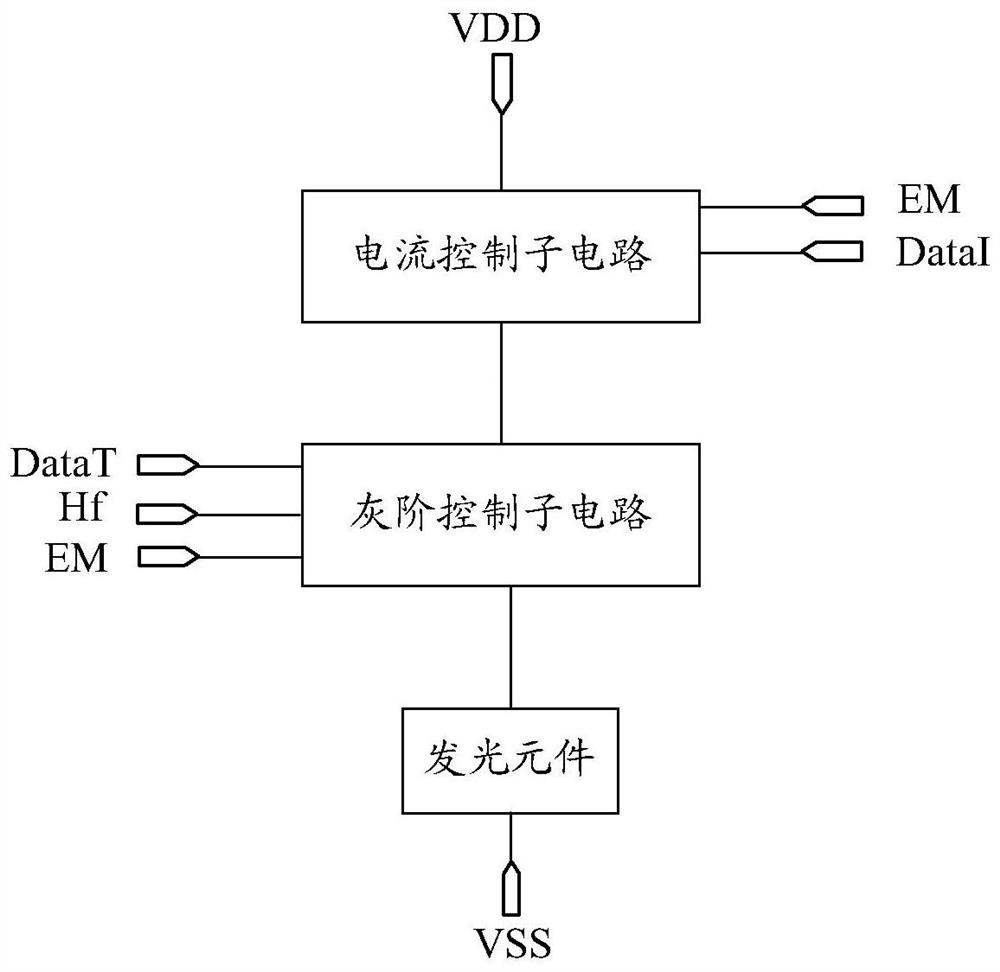
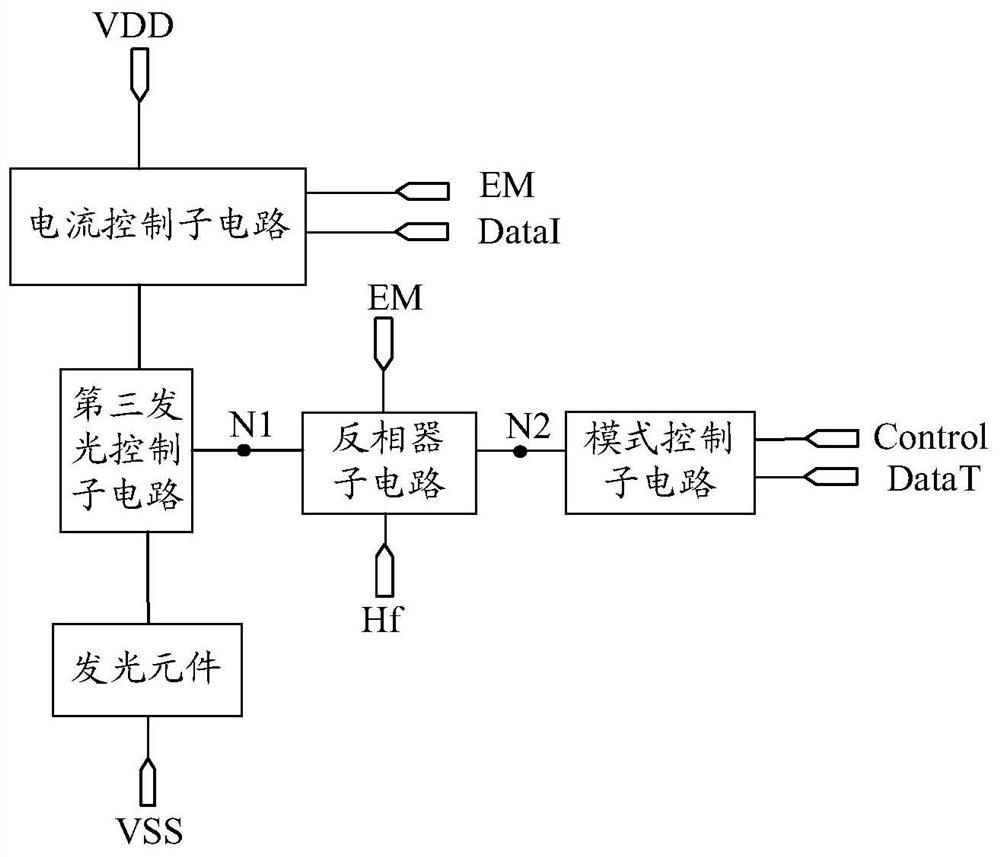
The invention discloses a pixel circuit and a driving method thereof and a display device. The pixel circuit comprises a current control sub-circuit and a gray scale control sub-circuit; the current control sub-circuit is used for receiving a display data signal and a light-emitting control signal and controlling whether to generate a driving current or not according to the light-emitting control signal, and controlling the current intensity of the generated driving current according to the display data signal; the gray scale control sub-circuit is used for receiving the mode control signal and the generated driving current, and when the mode control signal is in a first display mode, the light-emitting element is driven in a first duration; when the mode control signal is in a second display mode, the light-emitting element is driven in a second duration, and at least one of the first duration and the second duration is composed of a plurality of pulse periods. According to the invention, the light-emitting element is driven in different durations according to different display modes, and at least one of the different durations is composed of a plurality of pulse periods, so when the gray scale is low, the light-emitting time can be dispersed in the light-emitting stage, and the flicker phenomenon of the low gray scale is avoided.

Description

technical field [0001] Embodiments of the present disclosure relate to but are not limited to the field of display technologies, and in particular, relate to a pixel circuit, a driving method thereof, and a display device. Background technique [0002] Micro Light Emitting Diode (Micro LED) technology integrates a micro-sized LED array on a chip at a high density to achieve thinning, miniaturization and matrixing of LEDs, and the distance between pixels can reach microns level, and each pixel can be addressed and illuminated individually. Due to its low driving voltage, long life, and wide temperature resistance, Micro LED display panels are gradually developing into display panels used in consumer terminals. [0003] Usually, the pixel circuit is electrically connected to the Micro LED to drive the Micro LED to emit light. In the related pixel circuit, the gray scale is usually adjusted by the current and the luminous time. However, the adjustment of the gray scale by the...

Claims


Application Information

Patent Timeline
Patent Type & Authority Applications(China)
IPC IPC(8): G09G3/32
CPCG09G3/32G09G2340/0407
Inventor 陈亮刘冬妮肖丽郑皓亮韩承佑玄明花赵蛟陈昊
Owner BOE TECH GRP CO LTD
Learn More