A top-blowing and bottom-blowing dual-purpose smelting device

A top-blowing and converter technology, which is applied in the manufacture of converters and the improvement of process efficiency, etc., can solve the problems of poor flexibility, complicated operation, complex structure, etc., and achieve the effect of eliminating the dead zone of stirring, increasing the degree of stirring, and reducing investment

Active Publication Date: 2022-06-07
浙江友谊新材料有限公司
View PDF4 Cites 0 Cited by
  • Summary
  • Abstract
  • Description
  • Claims
  • Application Information

AI Technical Summary

Problems solved by technology

[0008] However, the existing compound-blowing converters generally include a furnace mouth for top blowing and a bottom blowing gas supply structure at the bottom. The bottom blowing gas supply structure directly opens gas supply holes on the furnace body. During the blowing process, the furnace body is kept Fixed, that is, the top blowing device and the bottom blowing device cannot follow the rotation of the converter, resulting in a certain dead zone of stirring in the furnace. Once the blowing starts, it cannot be easily adjusted, and the flexibility of use is poor; the top blowing system and the bottom blowing system are separated from each other , not only the structure is complicated, the operation is complicated, but also the difficulty of on-site construction layout is increased

Method used


Image

  • A top-blowing and bottom-blowing dual-purpose smelting device
  • A top-blowing and bottom-blowing dual-purpose smelting device
  • A top-blowing and bottom-blowing dual-purpose smelting device

Examples


Embodiment Construction

[0032] The present invention will be further described below with reference to the accompanying drawings.

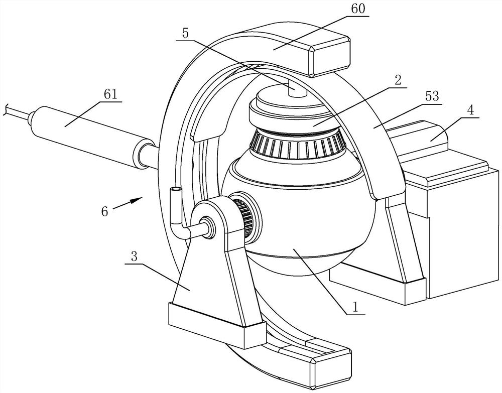
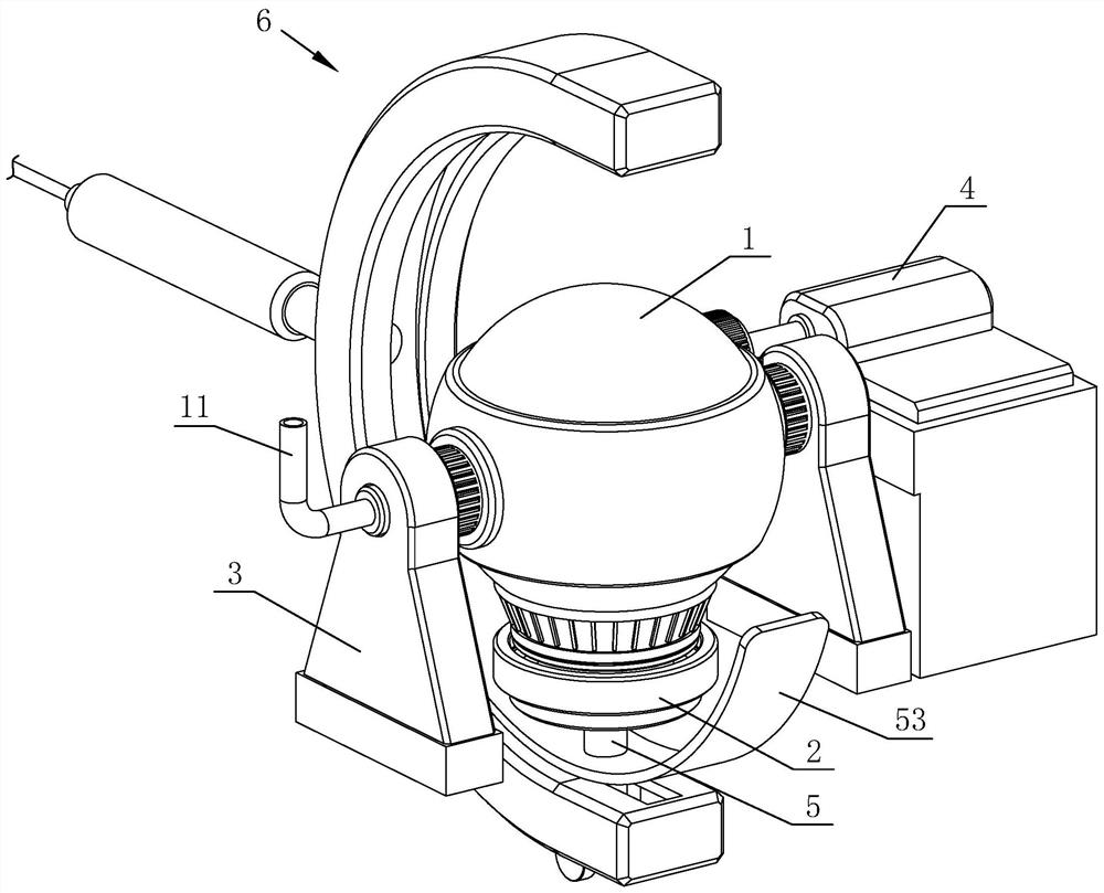
[0033] like figure 1 and figure 2 The shown top-blowing and bottom-blowing dual-purpose smelting device includes a converter 1, a furnace cover 2, a support 3 for supporting the converter 1, a drive mechanism 4 for driving the converter to rotate, a blowing mechanism 5 and a pipeline control mechanism 6 The furnace body of the converter 1 is spherical, and the converter 1 is rotatably connected with the support 3. In the natural state, the furnace mouth of the converter 1 faces directly upward, and the driving mechanism 4 can drive the converter 1 to rotate 180° so that the furnace mouth faces directly downward. The furnace cover 2 and the blowing mechanism 5 can move synchronously with the rotation of the converter 1, and the pipeline control mechanism 6 is used to limit and guide the movement path of the pipelines used for blowing. When the furnace mouth of the conv...


PUM


Abstract

The invention discloses a top-blowing and bottom-blowing dual-purpose smelting device, which includes a converter, a furnace cover, a support, a driving mechanism for driving the converter to rotate, and a blowing mechanism. The body of the converter is spherical, and the converter is connected to the support in rotation. , the interior of the converter is provided with a refractory lining, and the connection between the converter and the support is provided with a discharge pipe for exhausting the flue gas. The blowing mechanism includes a top blowing pipe, a bottom blowing structure and an air intake pipe. On the cover, the top blowing pipe is set concentrically with the furnace cover, the top blowing pipe is provided with a refractory coating, the bottom blowing structure is arranged inside the furnace cover, the bottom blowing structure is cylindrical, the bottom blowing structure can be inserted into the furnace mouth of the converter and the bottom blowing structure The outer wall is close to the inner wall of the furnace mouth. The bottom blowing structure is made of the same material as the refractory lining. The bottom blowing structure has multiple air holes, all of which are connected to the intake pipe. The furnace cover and blowing mechanism can move synchronously with the rotation of the converter. , The blowing mechanism is also equipped with a pipeline control mechanism for limiting the movement path of the intake pipe.

Description

technical field [0001] The invention relates to the field of metal smelting, in particular to a top-blowing and bottom-blowing dual-purpose smelting device. Background technique [0002] Converter steelmaking (ConverterSteelmaking) takes molten iron, scrap steel and ferroalloy as the main raw materials, without external energy, relying on the physical heat of the molten iron itself and the chemical reaction between the components of the molten iron to generate heat to complete the steelmaking process in the converter. It is used in the production of carbon steel, alloy steel and the smelting of copper and nickel. Converters are classified into acidic and basic types according to refractory materials. There are top blowing, bottom blowing and side blowing according to the parts where the gas is blown into the furnace. According to the type of gas, there are air converters and oxygen converters. [0003] The top blowing method is to insert an oxygen lance into the furnace fro...

Claims


Application Information

Patent Timeline
Patent Type & Authority Patents(China)
IPC IPC(8): C21C5/35C21C5/46
CPCC21C5/35C21C5/4606C21C5/46Y02P10/20
Inventor 杨伟标胡涛滕松成
Owner 浙江友谊新材料有限公司
Why Eureka
Try Eureka