
Large component surface impact shot blasting system and method

A large-scale component and shot peening technology, which is applied in the direction of spray guns, abrasive jet machine tools, used abrasive processing devices, etc., can solve the problems of shortening the shot peening operation time, shorten the shot peening operation time, and improve the shot peening processing efficiency , Improve the effect of shot peening coverage and processing accuracy

Pending Publication Date: 2021-06-18
无锡中车时代智能装备研究院有限公司
View PDF0 Cites 1 Cited by
  • Summary
  • Abstract
  • Description
  • Claims
  • Application Information

AI Technical Summary

Problems solved by technology

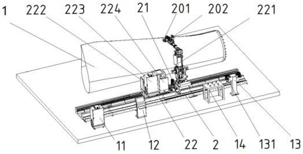
[0005] In view of the above defects or improvement needs of the prior art, the present invention provides a large component surface impact shot peening system, which adopts the method of clamping the impact shot peening device at the end of the industrial robot to perform shot peening on the surface of the large component. The end tool of the industrial robot can It is a single impact shot peening device, and it can also flexibly combine impact shot peening devices of different specifications, and the impact head of the impact shot peening device can also be replaced flexibly; in addition, the system also integrates visual measurement, dust removal system and shot peening process, It greatly shortens the shot blasting operation time, improves the processing efficiency and processing quality, improves the working environment on site, and liberates workers from the harsh working environment; The shot peening device integrates surface measurement and shot peening processing of large components, which can solve the problem of inability to achieve efficient and high-quality shot peening on the surface of large components in the prior art, and greatly improves the surface blasting of large components. Efficiency and quality of pills, great creativity

Method used


Image

  • Large component surface impact shot blasting system and method
  • Large component surface impact shot blasting system and method
  • Large component surface impact shot blasting system and method

Examples


Embodiment Construction

[0049] In order to make the object, technical solution and advantages of the present invention clearer, the present invention will be further described in detail below in conjunction with the accompanying drawings and embodiments. It should be understood that the specific embodiments described here are only used to explain the present invention, not to limit the present invention. In addition, the technical features involved in the various embodiments of the present invention described below can be combined with each other as long as they do not constitute a conflict with each other.

[0050] It should be noted that when an element is referred to as being “fixed” or “disposed on” another element, it may be directly on the other element or be indirectly on the other element. When an element is referred to as being "connected to" another element, it can be directly connected to the other element or indirectly connected to the other element.

[0051] In addition, the terms “firs...


PUM


Abstract

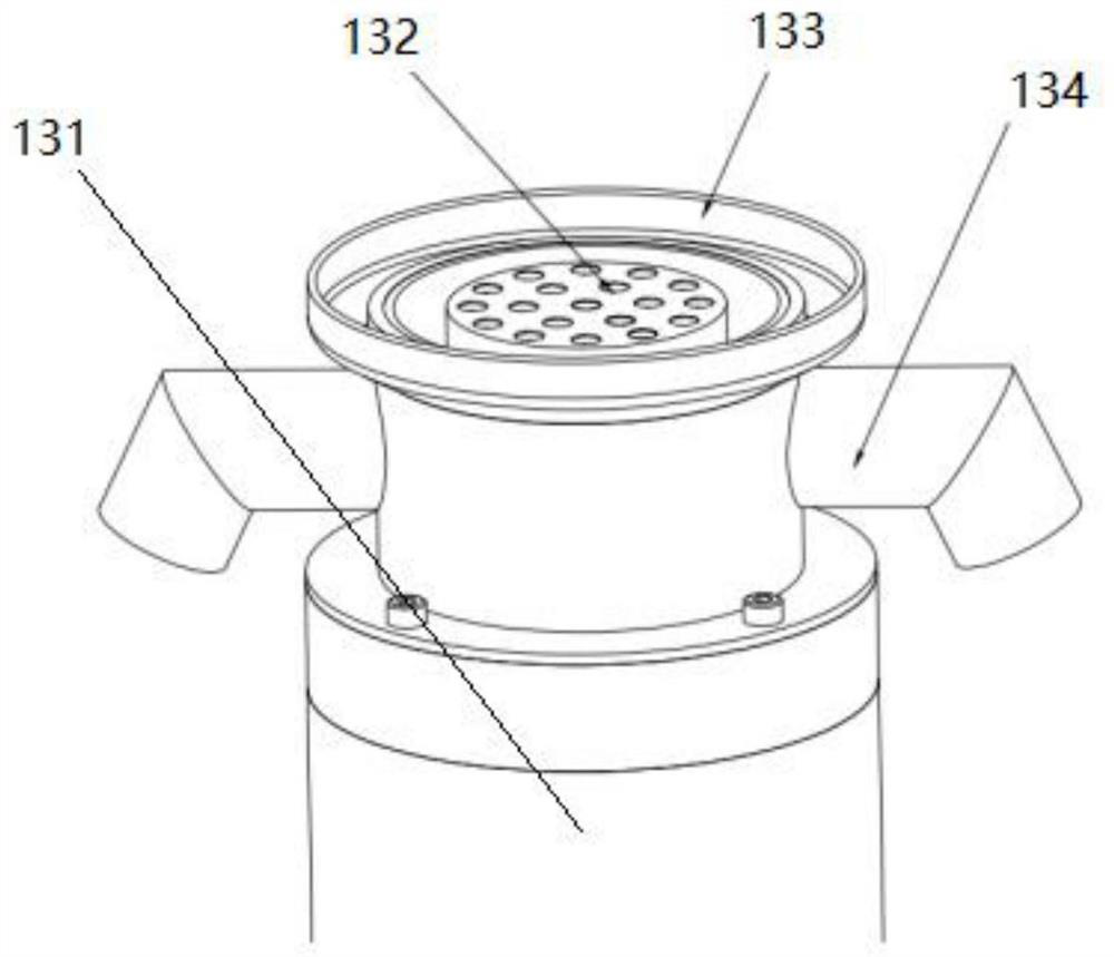
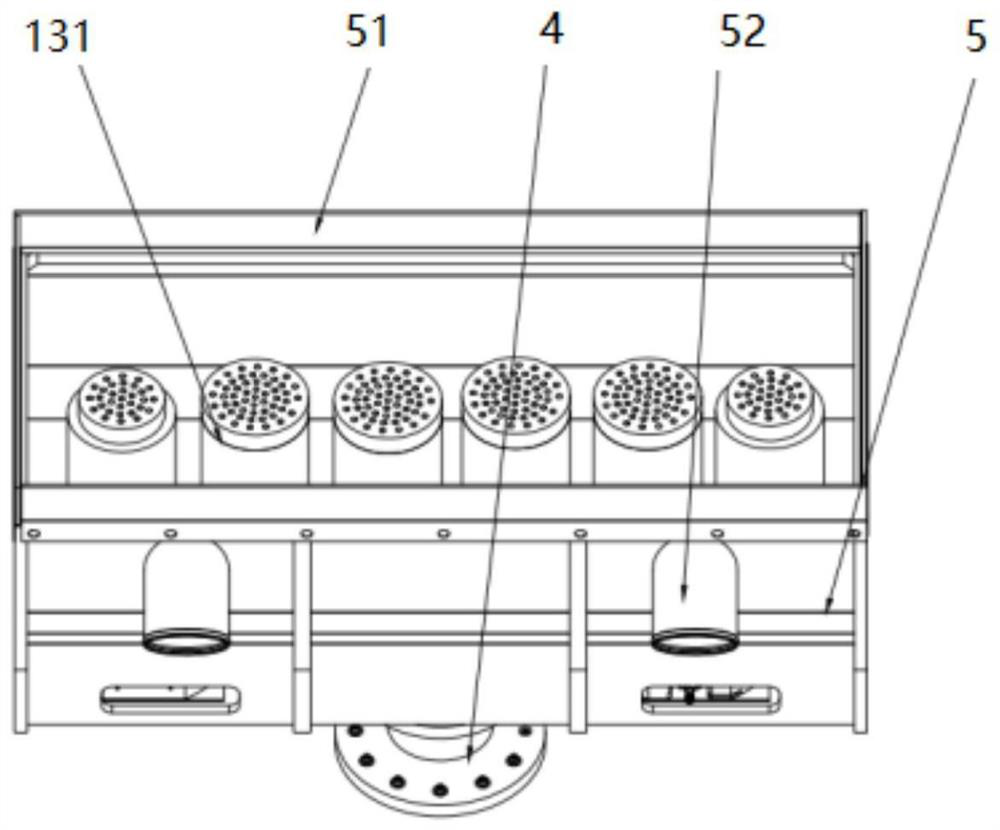
The invention discloses a large component surface impact shot blasting system and method. The system comprises a robot horizontal guide rail, a horizontal guide rail motor, a guide rail carrying table, an industrial robot installed on the guide rail carrying table, a robot control cabinet, a remote control cabinet, a dust collector, a quick change tool installed at the tail end of an arm of the industrial robot and visual inspection equipment, and further comprises an electric control cabinet, an industrial control all-in-one machine and a support for mounting the impact shot blasting device and the impact head, which are mounted at one side of the robot industrial guide rail. The tail end of the industrial robot is used for clamping the impact shot blasting device to conduct shot blasting operation on the surface of the large component; a single impact shot blasting device is adopted, or the impact shot blasting devices of different specifications are flexibly combined together, and impact heads of the impact shot blasting devices can also be flexibly replaced. In addition, the system also integrates visual measurement, a dust removal system and a shot blasting process, so that the shot blasting operation time is greatly shortened, the processing efficiency and the processing quality are improved, the field working environment is improved, and the system is extremely creative.

Description

technical field [0001] The invention belongs to the technical field of shot peening, and more specifically relates to a large component surface impact shot peening system and method. Background technique [0002] Shot peening is a surface strengthening process widely used in factories. Its equipment is simple, low in cost, not limited by the shape and position of the workpiece, and easy to operate, but the working environment is poor. Shot peening is widely used to improve the mechanical strength, wear resistance, fatigue resistance and corrosion resistance of parts, etc. It can also be used for surface matting, descaling and elimination of residual stress in casting, forging and welding parts. Shot peening technology is to use high-speed projectile flow to hit the surface of the metal plate, so that the impacted surface and the underlying metal material will be plastically deformed and extended, so that the plate will gradually bend and deform toward the sprayed surface to ...

Claims


Application Information

Patent Timeline
IPC IPC(8): B24C1/08B24C1/10B24C3/00B24C5/04B24C9/00
CPCB24C1/086B24C1/10B24C3/00B24C5/04B24C9/00
Inventor 严思杰郑志伟李克宁
Owner 无锡中车时代智能装备研究院有限公司
Learn More