
Improved current prediction control method of switched reluctance motor

A technology of switched reluctance motor and control method, which is applied in the direction of motor generator control, AC motor control, electronic commutation motor control, etc., and can solve the problems of lacking, ignoring the nonlinear characteristics of switched reluctance motor, and the control is not delicate, etc. Achieve the effects of reducing current overshoot, realizing high-performance operation, and reducing the amount of calculation

Active Publication Date: 2021-06-15
DALIAN UNIV OF TECH
View PDF8 Cites 1 Cited by
  • Summary
  • Abstract
  • Description
  • Claims
  • Application Information

AI Technical Summary

Problems solved by technology

[0004] However, the current PI control ignores the nonlinear characteristics of the switched reluctance motor, so that the current control has a certain overshoot
Current PI control cannot meet the requirements when the motor control has high speed and control accuracy requirements, and there is still no effective theory to determine the values ​​of various parameters for PI parameter setting at this stage. In practice, a large number of simulations and experiments are usually relied on. adjustments, which again presents some problems for motor control
Model predictive control also has some disadvantages
A large amount of calculation is a disadvantage, which puts high demands on the computing power of the control board
Although rolling optimization is possible, the control accuracy is poor, and the control is not delicate enough to achieve high control accuracy and cannot eliminate the static error of the system
At the same time, there is a high precision requirement for the sampling time, the sampling frequency is low, and the motor cannot be effectively controlled at about 10kHz

Method used


Image

  • Improved current prediction control method of switched reluctance motor
  • Improved current prediction control method of switched reluctance motor
  • Improved current prediction control method of switched reluctance motor

Examples


Embodiment Construction

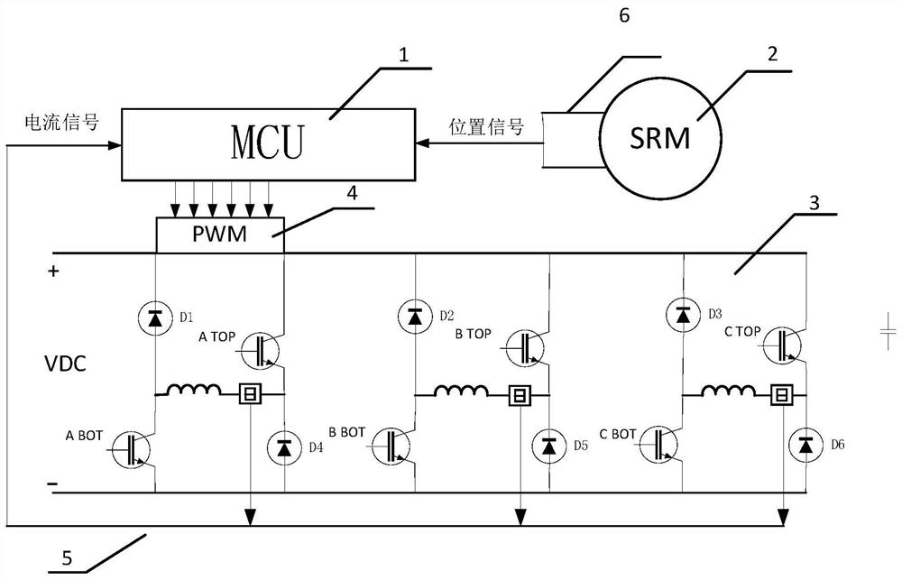
[0045] The specific embodiment of the present invention is as figure 1 As shown, the microcontroller 1 is STM32F030C6, and the power converter 3 adopts a three-phase asymmetrical half-bridge structure. The switched reluctance motor is a 12 / 8-pole three-phase switched reluctance motor 2 with a rated speed of 2200r / min. It is powered by a power converter 3, and the current is detected by a current sensor and a current detection filter circuit 5, and is input to the microcontroller The ADC0 port of the device 1, the position detection unit 6 (position sensor) is composed of the rotor position measurement tooth disc, two slot-type Hall switch devices and corresponding circuits. Microcontroller 1 obtains the state of the two Hall switches by inputting the capture interrupt to determine the current position of the rotor.

[0046] The switched reluctance motor adopts double closed-loop control of speed and current. The actual speed of the motor and the current position of the rotor...


PUM


Abstract

The invention discloses an improved current prediction control method of a switched reluctance motor, and belongs to the technical field of switched reluctance motor control. A system for completing the control method comprises a microcontroller, a three-phase switched reluctance motor, a power converter, a PWM driving unit, a current sensor, a current detection filter circuit and a position detection unit; the main circuit of the PWM driving unit is of a three-phase asymmetric half-bridge structure; According to a switched reluctance driving system, a double-closed-loop control system is adopted, an outer loop employs rotating speed loop control, an actual rotating speed is calculated through a position detection unit, and a reference current is obtained through a PI controller after the difference between a reference rotating speed and the actual rotating speed is obtained; an inner loop employscurrent loop control, the relation among inductance, current and a rotor position angle is obtained through finite element analysis, and corresponding phase inductance values and control frequency of the motor are obtained through phase current and the rotor position angle through a two-dimensional look-up table method. A corresponding predicted current interval is obtained through the above conditions, and then the precise time of each switching state is calculated to serve as a PWM conduction signal of a conduction phase to be used for driving the motor.

Description

technical field [0001] The invention belongs to the technical field of switched reluctance motor control, and mainly aims at the problem that the current is difficult to control within the limited current sampling frequency and control frequency caused by the nonlinear characteristics of switched reluctance motor inductance, and a method for improving the accuracy of current control. Background technique [0002] A switched reluctance motor (Switched Reluctance Motor, SRM) has excellent characteristics such as low manufacturing cost, simple structure of the stator and rotor, and good fault tolerance. The motor speed control system generally adopts double closed-loop control of speed and current. Commonly used current loop control methods include current PI control, model predictive current control and other methods. [0003] The current PI control principle is simple, easy to use, strong adaptability, and less sensitive to current changes of the controlled object. When pay...

Claims


Application Information

Patent Timeline
IPC IPC(8): H02P21/22H02P21/00H02P25/098H02P25/092H02P25/08
CPCH02P21/22H02P21/0003H02P25/098H02P25/092H02P25/0805
Inventor 白凤仙杜呼和孙建忠
Owner DALIAN UNIV OF TECH
Learn More