
Compressor

A technology for compressors and housings, which is applied in the field of compressors with moving strokes, which can solve problems such as the decrease in the accuracy of piston sensing, the difficulty of accurately measuring strokes, and the inability to compensate engine loads, etc., to achieve the effect of improving control stability

Active Publication Date: 2020-09-04
HANON SYST +1
View PDF12 Cites 0 Cited by
  • Summary
  • Abstract
  • Description
  • Claims
  • Application Information

AI Technical Summary

Problems solved by technology

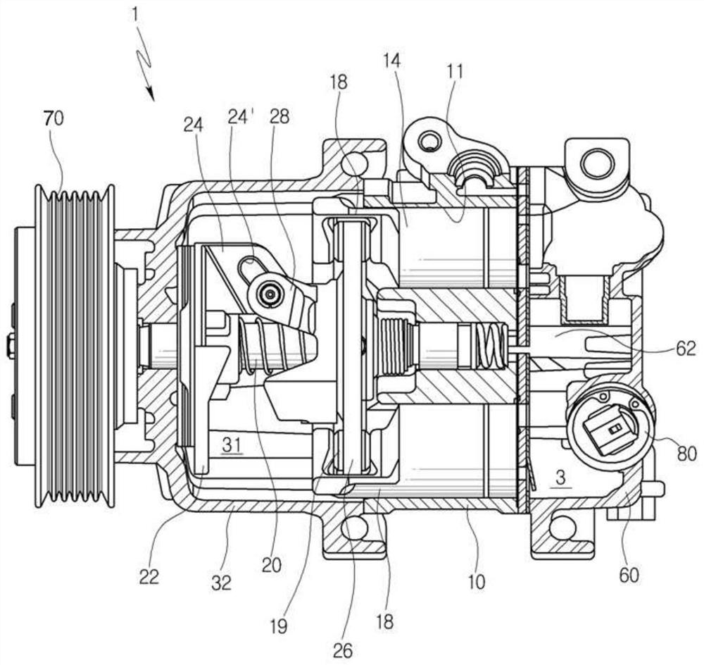
[0019] In the variable swash plate type compressor used in this way, it is difficult to accurately measure the stroke when the piston (14) reciprocates, resulting in a situation where accurate engine load compensation cannot be performed according to the various loads generated. question
[0020] Recently, although various methods have been tried to accurately measure the moving stroke of the piston, the above-mentioned problem of a decrease in the sensing accuracy of the piston has arisen

Method used


Image

  • Compressor
  • Compressor
  • Compressor

Examples


Embodiment Construction

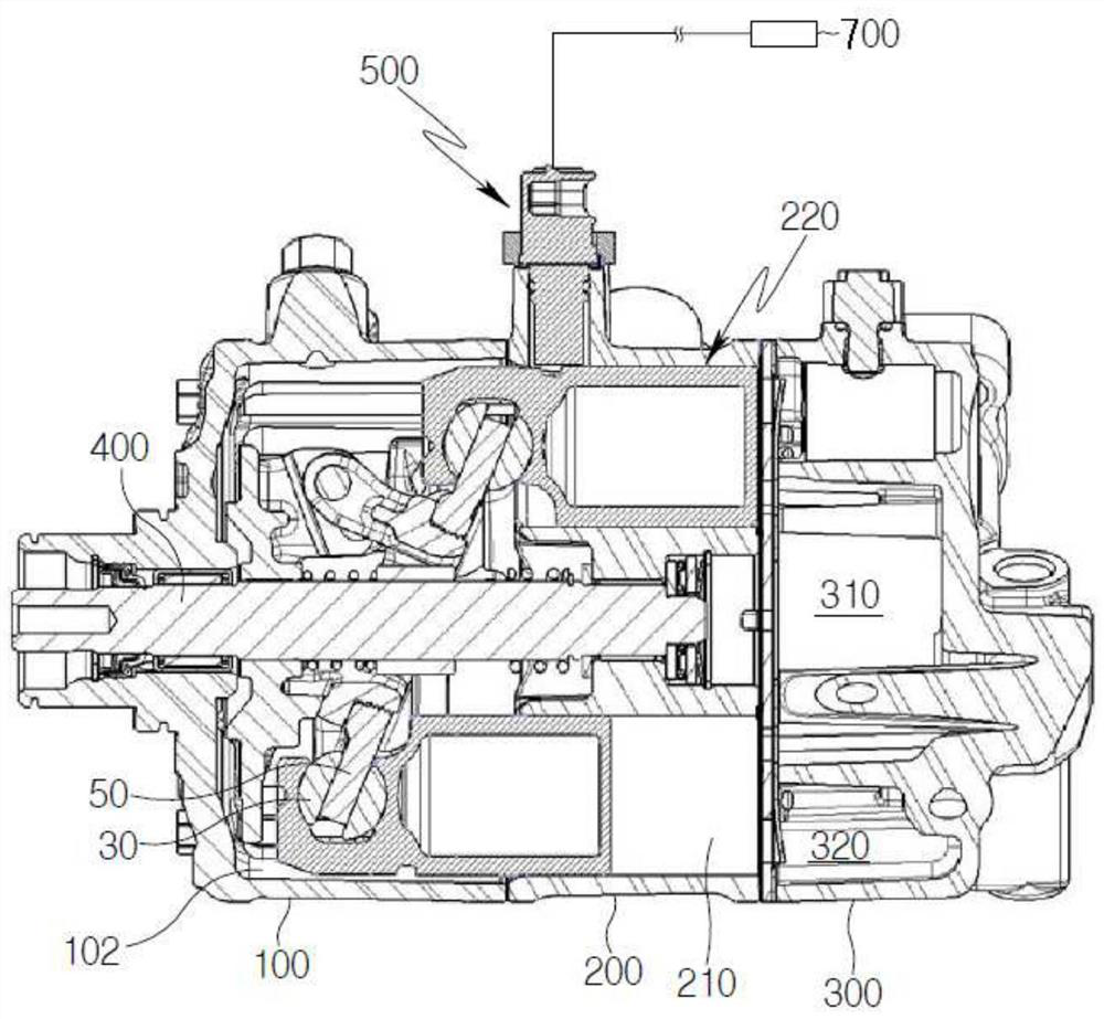
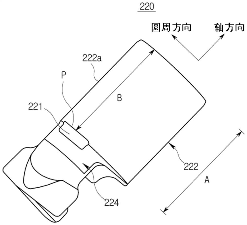
[0066] Hereinafter, a compressor according to a first embodiment of the present invention will be described in detail with reference to the accompanying drawings. figure 2 To show a sectional view of the compressor of the first embodiment of the present invention, image 3 To show a perspective view of the piston provided in the compressor of the first embodiment of the present invention, Figure 4 for image 3 longitudinal section view.

[0067] refer to Figure 2 to Figure 4 , when the compressor of the first embodiment of the present invention works under various load conditions, the stroke data of the piston 220 is accurately measured according to the swash plate angle of the swash plate, and the torque based on the load fluctuation of the above-mentioned compressor is compensated by performing real-time monitoring , thereby improving fuel economy.

[0068] In addition, the sensor unit 500 described later in this embodiment accurately measures the separation distance ...


PUM


Abstract

The invention relates to a compressor. The compressor of this embodiment controls the load of the compressor by accurately calculating the movement stroke and period of a piston.

Description

technical field [0001] The present invention relates to a compressor, and in more detail, the present invention relates to a compressor for accurately detecting a moving stroke of a piston. Background technique [0002] The refrigeration unit of the car includes a compressor, a condenser, an expansion valve, and an evaporator. The compressor (Compressor) compresses the refrigerant gas discharged from the evaporator into a high-temperature and high-pressure state that is easy to liquefy and transmits it to the condenser. And, the compressor plays a role of sucking and recirculating the refrigerant so as to continuously perform refrigeration. [0003] The condenser (condenser) cools and liquefies the refrigerant by exchanging heat between the high-temperature and high-pressure refrigerant gas and the outside air, and the expansion valve (expansion valve) lowers the temperature and pressure by adiabatically expanding the liquid refrigerant, thereby It plays the role of changin...

Claims


Application Information

Patent Timeline
Patent Type & Authority Applications(China)
IPC IPC(8): F04B27/08F04B39/00F04B51/00F04B49/12F04B27/22
CPCF04B27/0878F04B27/0873F04B39/0005F04B51/00F04B49/12F04B27/22F04B2201/0202F04B2201/0206F04B27/1036F04B27/16F04B2201/0201F05B2210/14F05B2270/30F01B3/0017F01B31/12
Inventor 郭荣明金永熙丹尼尔·多姆克西蒙·舍纳彼得·库尔特·扎瓦兹基
Owner HANON SYST
Learn More