
Duty cycle regulating circuit and duty cycle regulating method

A technology for adjusting the circuit and duty cycle, which is applied in the direction of electrical components, electric pulse generation, pulse generation, etc., can solve the problems of complex clock channel circuit, difficult layout, complex structure of duty cycle adjustment circuit, etc., and achieve simple circuit structure , the effect of precise duty cycle

Active Publication Date: 2014-09-03
IPGOAL MICROELECTRONICS (SICHUAN) CO LTD
View PDF6 Cites 0 Cited by
  • Summary
  • Abstract
  • Description
  • Claims
  • Application Information

AI Technical Summary

Problems solved by technology

[0003] However, the structure of the traditional duty ratio adjustment circuit is relatively complex, and peripheral circuits are required to provide bias, so that the circuit of the clock path is more complicated, and in the integrated circuit, it brings difficulties to the layout

Method used


Image

  • Duty cycle regulating circuit and duty cycle regulating method
  • Duty cycle regulating circuit and duty cycle regulating method

Examples


Embodiment Construction

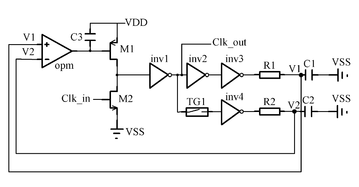
[0015] See figure 1 , The preferred embodiment of the duty cycle adjustment circuit of the present invention includes an operational amplifier opm, a first switching element, a second switching element, a first inverter inv1, a second inverter inv2, a third inverter Phaser inv3, a fourth inverter inv4, a transmission gate TG1, a first resistor R1, a second resistor R2, a first capacitor C1, a second capacitor C2, a third capacitor C3, and a clock signal The input terminal Clk_in, a clock signal output terminal Clk_out, a power terminal VDD and a ground terminal VSS.

[0016] In this embodiment, the first switching element is a first field effect transistor M1, and the second switching element is a second field effect transistor M2. The first field effect transistor M1 is a P-type field effect transistor (PMOS), and the second field effect transistor M2 is an N-type field effect transistor (NMOS). In other embodiments, the switching element can be changed to a switching element o...


PUM


Abstract

The invention provides a duty cycle regulating circuit. The duty cycle regulating circuit comprises an operational amplifier, a first switching element connected with the operational amplifier, a clock signal input terminal, a second switching element connected with the clock signal input terminal, a first inverter connected with the first switching element and the second switching element, a second inverter connected with the first inverter, a third inverter connected with the second inverter, a first resistor connected with the third inverter, a first capacitor connected with the first resistor, a transmission gate connected with the first inverter, a fourth inverter connected with the transmission gate, a second resistor connected with the fourth inverter, a second capacitor connected with the second resistor, and a clock signal output terminal connected with the first inverter, wherein, a positive phase input terminal of the operational amplifier is connected between the first resistor and the first capacitor, and an inverse phase input terminal of the operational amplifier is connected between the second resistor and the second capacitor. The invention further provides a duty cycle regulating method. The duty cycle regulating circuit has a simple structure, and the duty cycle of the generated clock signal is accurate.

Description

Technical field [0001] The invention relates to an adjustment circuit and an adjustment method, in particular to a duty ratio adjustment circuit and a duty ratio adjustment method that can adjust the duty ratio of an output clock signal to 50%. Background technique [0002] The duty cycle adjustment circuit is very important for the transmission of high-speed clock signals. The traditional duty cycle adjustment circuit is generally implemented by adjusting the switching threshold of signal transmission. By increasing or decreasing the switching threshold, the pulse width of high and low levels is changed. So as to realize the adjustment of the duty cycle. [0003] However, the structure of the traditional duty cycle adjustment circuit is complicated, and the peripheral circuit is required to provide bias, which makes the circuit of the clock path more complicated, and in the integrated circuit, it brings difficulties to the layout. Summary of the invention [0004] In view of the a...

Claims


Application Information

Patent Timeline
Patent Type & Authority Patents(China)
IPC IPC(8): H03K3/017
Inventor 范方平
Owner IPGOAL MICROELECTRONICS (SICHUAN) CO LTD
Learn More