
Polishing slurry composition and method for producing same

A technology of composition and slurry, which is applied to polishing compositions containing abrasives, chemical instruments and methods, and other chemical processes, can solve the problems of scratches on polishing particles, adjust flatness and control, and achieve excellent polishing rate, improve flatness, and prevent dents and scratches

Inactive Publication Date: 2021-06-08
K C TECH
View PDF8 Cites 0 Cited by
  • Summary
  • Abstract
  • Description
  • Claims
  • Application Information

AI Technical Summary

Problems solved by technology

On the one hand, the use of a single-layer slurry of a mixture of anionic polymers and anionic copolymers can achieve a selectivity ratio and a high polishing rate in the high step region, but it is difficult to adjust the flatness and control in the low step region. sunken
Also, scratches can be a problem due to the inherent hardness of the polishing particles

Method used


Image

  • Polishing slurry composition and method for producing same
  • Polishing slurry composition and method for producing same
  • Polishing slurry composition and method for producing same

Examples


preparation example Construction

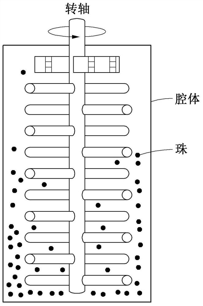
[0093] A method for preparing a polishing slurry composition according to another embodiment of the present invention includes the steps of: dispersing polishing particles such that the surface of the particles has a positive charge, a first dispersant comprising a nonionic linear polymer, and a first dispersant comprising an anion a step of preparing a polishing slurry by mixing a second dispersant of a linear coil polymer; and a step of grinding the polishing slurry using beads.

[0094] And, according to the preparation method of the polishing slurry composition of the present invention, the primary particle size of the polishing particles is controlled by adjusting the grinding energy during the grinding process, based on the reduction of the particle size, preventing dents and scratches from occurring during polishing, reducing the number of processes, Increase productivity.

[0095] According to one aspect, the grinding is performed using beads with a diameter ranging fr...

Embodiment 1

[0119] In Example 1, Example 2, Comparative Example 1 and Comparative Example 2, the silicon pattern wafer was polished under the following polishing conditions.

[0120] [Polishing condition]

[0121] 1. Polishing device: AP-300 (CTS company)

[0122] 2. Pad: K7 (Rohm&Hass)

[0123] 3. Polishing time: 60s

[0124] 4. Platen speed: 93

[0125] 5. Spindle speed: 87

[0126] 6. Flow rate: 250ml / min

[0127] 7. Chip pressure: 3.0psi

[0128] 8. Chips used:

[0129] PE-TEOS LP-Nitride P-doped polymer (P_DopedPoly)

[0130] STI Nitride Pattern (Nitride Pattern) HDP Trench )

[0131] Show respectively in the following table 2 the grinding energy of embodiment 1, embodiment 2, comparative example 1 and comparative example 2, the polishing characteristic (grinding energy=rotating shaft grinding speed (rpm) in the polishing slurry composition after polishing and polishing × bead filling rate (%)). Particle size is the size measured by XRD.

[0132] 【Table 2】

[...


PUM

PropertyMeasurementUnit
diameteraaaaaaaaaa
particle sizeaaaaaaaaaa
diameteraaaaaaaaaa

Abstract

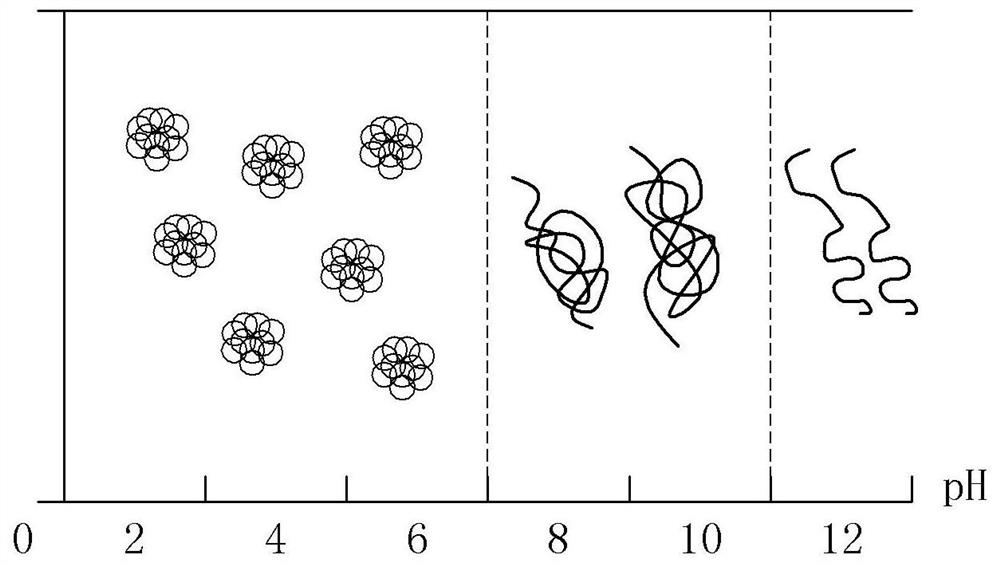
The present invention relates to a polishing slurry composition and a method for producing same. The polishing slurry composition according to one embodiment of the present invention comprises: polishing particles dispersed so as to have positively-charged particle surfaces; a first dispersant comprising a non-ionic linear polymer; and a second dispersant comprising an anionic coiling polymer, wherein the polishing slurry composition satisfies [Expression 1] and [Expression 2]. [Expression 1] 4 <= log(milling energy) < 5, [Expression 2] 20% <= decrease rate (%) in first particle size < 35%.

Description

technical field [0001] The invention relates to a polishing slurry composition and a preparation method thereof. Background technique [0002] As semiconductor elements become more diverse and highly integrated, a technology capable of forming fine patterns is used, which makes the surface structure of semiconductor elements more and more complicated, and the step difference of the surface film becomes larger and larger. In the process of manufacturing semiconductor elements, chemical mechanical polishing (CMP, chemical mechanical polishing) planarization technology is used to remove the step difference formed on a specific film of a substrate. Insulation for shallow trench isolation (STI) that is used as a process for removing excessively formed insulating films for interlayer insulation and insulation between interlayer insulating films (interlayer dielectric, ILD) and chips (chips). It is used in the planarization process of the film and the process of forming metal cond...

Claims


Application Information

Patent Timeline
Patent Type & Authority Applications(China)
IPC IPC(8): C09G1/02C09K3/14
CPCC09G1/02C09K3/1436C09K3/1409C09K3/1454C09K3/14
Inventor 朴光洙黄晙夏崔秀完崔洛炫
Owner K C TECH
Learn More