
Catalytic combustion treatment device for adsorbed waste gas

A catalytic combustion and treatment device technology, which is applied in the direction of combustion method, combustion type, incinerator, etc., can solve the problems that the activated carbon plate cannot be fully and effectively used, and the exhaust gas cannot be fully dispersed.

Pending Publication Date: 2021-06-08
杭州杭大环保工程有限公司
View PDF0 Cites 0 Cited by
  • Summary
  • Abstract
  • Description
  • Claims
  • Application Information

AI Technical Summary

Problems solved by technology

[0003] Adsorption and catalytic combustion are commonly used methods for waste gas treatment. Existing devices generally use activated carbon plates to absorb the exhaust gas entering the intake pipe. Adsorption can be carried out, and the activated carbon plate cannot be fully and effectively used

Method used


Image

  • Catalytic combustion treatment device for adsorbed waste gas
  • Catalytic combustion treatment device for adsorbed waste gas

Examples


Embodiment 1

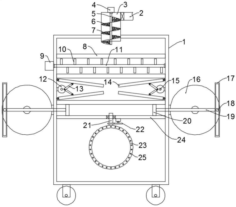
[0024] see figure 1 , In the embodiment of the present invention, a catalytic combustion treatment device for adsorbing exhaust gas includes a box body 1. The bottom of the box body 1 is evenly and symmetrically fixed with rollers to facilitate the movement of the device. A box door is installed on the box body 1. Preferably, it is connected to the box body 1 through hinges and buckles. The box body 1 is divided into an adsorption chamber and a catalytic combustion chamber by a horizontally arranged partition plate 24. The partition plate 24 is provided with a communication pipe 21 for connecting the adsorption chamber and the catalytic combustion chamber. , the adsorption chamber is located above the catalytic combustion chamber, and an air intake unit is installed on the top of the box 1 . In this embodiment, the air intake unit includes a dispersion cylinder 3 , a first motor 4 , a first rotating shaft 5 and auger blades 6 The dispersion cylinder 3 is fixedly installed on t...

Embodiment 2

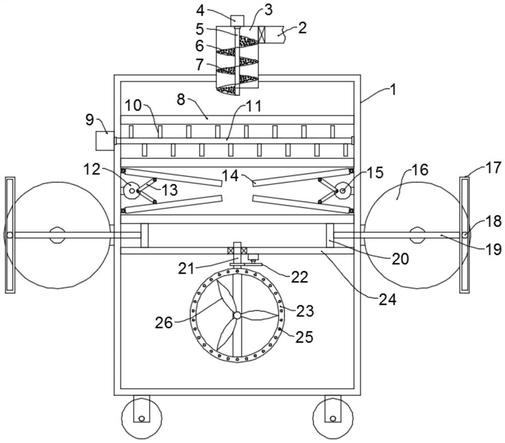
[0028] see figure 2, In the embodiment of the present invention, a catalytic combustion treatment device for adsorbing exhaust gas includes a box body 1. The bottom of the box body 1 is evenly and symmetrically fixed with rollers to facilitate the movement of the device. A box door is installed on the box body 1. Preferably, it is connected to the box body 1 through hinges and buckles. The box body 1 is divided into an adsorption chamber and a catalytic combustion chamber by a horizontally arranged partition plate 24. The partition plate 24 is provided with a communication pipe 21 for connecting the adsorption chamber and the catalytic combustion chamber. , the adsorption chamber is located above the catalytic combustion chamber, and an air intake unit is installed on the top of the box 1 . In this embodiment, the air intake unit includes a dispersion cylinder 3 , a first motor 4 , a first rotating shaft 5 and auger blades 6 The dispersion cylinder 3 is fixedly installed on t...


PUM


Abstract

The invention discloses a catalytic combustion treatment device for adsorbed waste gas. The device comprises a box body, the interior of the box body is divided into an adsorption cavity and a catalytic combustion cavity through a horizontally-arranged partition plate, a communicating pipe used for making the adsorption cavity communicate with the catalytic combustion cavity is arranged on the partition plate, the adsorption cavity is located above the catalytic combustion cavity, and a gas inlet unit is installed at the top of the box body; and the gas inlet unit comprises a dispersion barrel, a first motor, a first rotating shaft and an auger blade, a plurality of first activated carbon plates are fixed in the adsorption cavity from top to bottom, a first dispersion mechanism is installed between every two adjacent first activated carbon plates, and second dispersion mechanisms are symmetrically installed between the other two adjacent first activated carbon plates. The device has the following beneficial effects that the first dispersion mechanisms and the second dispersion mechanisms are arranged to perform turbulent flow dispersion on the waste gas, so that the flowability of the waste gas is improved; and a third dispersing mechanism is arranged, waste gas can be evenly provided for the catalytic combustion cavity, and sufficient catalytic combustion is achieved.

Description

technical field [0001] The invention relates to the technical field of exhaust gas treatment, in particular to an adsorption exhaust gas catalytic combustion treatment device. Background technique [0002] Organic waste gas mainly comes from the waste gas discharged from the production process of the petroleum and chemical industries. It is characterized by large quantity, large fluctuation of organic content, flammable, certain toxicity, and some odors. The emission of chlorofluorocarbons can also cause ozone layer. And the organic waste gas generated in these production processes is difficult to deal with. [0003] Adsorption and catalytic combustion are common methods of exhaust gas treatment. The existing devices generally use activated carbon plates to adsorb the exhaust gas entering the intake pipe. However, because the size of the intake pipe is smaller than that of the activated carbon plate, the exhaust gas cannot be fully dispersed, so that the activated carbon pla...

Claims


Application Information

Patent Timeline
IPC IPC(8): F23G7/07F23J15/02
CPCF23G7/07F23J15/022Y02A50/20
Inventor 高尔金沈雯迪袁勇华李斯佳何凤仙
Owner 杭州杭大环保工程有限公司
Learn More