
High-linearity radio frequency power amplifier

A technology of radio frequency power and high linearity, applied in power amplifiers, amplifiers, improved amplifiers to reduce nonlinear distortion, etc., can solve problems such as limited gain compensation capability, decreased gain performance, and reduced gain performance

Pending Publication Date: 2021-06-04
WENZHOU UNIVERSITY
View PDF6 Cites 1 Cited by
  • Summary
  • Abstract
  • Description
  • Claims
  • Application Information

AI Technical Summary

Problems solved by technology

For example, a document 1 "A 60GHz CMOS PowerAmplifier With Built-in Pre-Distortion Linearizer," IEEE Microwave and Wireless Components Letters, vol.21, no.12, pp.676-678, Dec.2011. proposes a three Class CMOS RF power amplifier, the CMOS RF power amplifier improves the linearity of the RF power amplifier through cold-mode MOSFET linearization pre-distortion technology, and the cold-mode MOSFET has a drain-source voltage of zero (V DS =0), adding body bias technology in the circuit, using the body bias effect of the cold mode MOSFET to generate predistortion characteristics, to improve the gain extension capability of the radio frequency power amplifier, thereby improving the linearity of the power amplifier; but, In the above-mentioned CMOS RF power amplifier, the gain compensation capability provided by the cold mode MOSFET is limited, and many control voltage pins are required, so that the designed power amplifier needs more bias, and the gain performance will be greatly reduced as the linearity is improved.
Document 2 "A K-band poweramplifier with parasitic diode linearizer in 0.18-μm CMOS process using 1.8-Vsupply voltage," in 2016 IEEE International Symposium on Radio-Frequency Integration Technology (RFIT), Taipei, 2016, pp.1-3. A three-stage power amplifier for the K-band is proposed, which uses a parasitic diode linearization circuit, and the parasitic diode in the p-n junction of the NMOS is used as a predistortion linearizer and added to the circuit, thereby significantly eliminating the three-stage power amplifier. order intermodulation (IM3); although the three-stage power amplifier improves the linearity of the power amplifier to a certain extent, its gain performance is also greatly reduced

Method used


Image

  • High-linearity radio frequency power amplifier
  • High-linearity radio frequency power amplifier
  • High-linearity radio frequency power amplifier

Examples


Embodiment

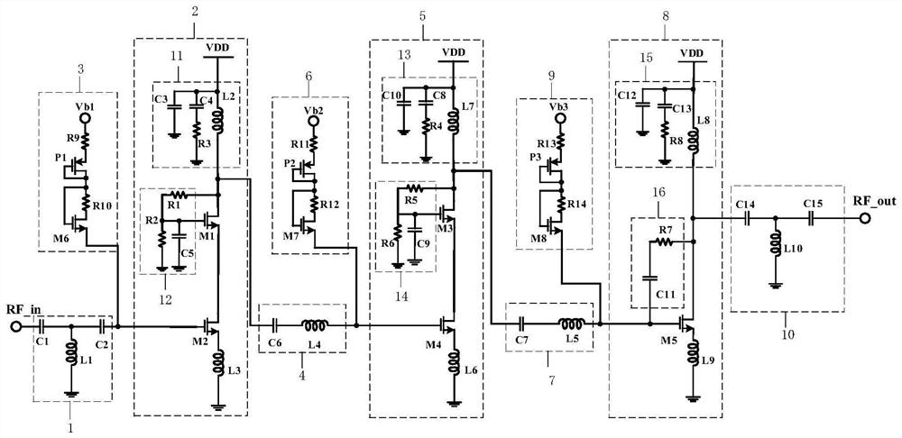
[0022] Example: such as figure 1 As shown, a high-linearity RF power amplifier includes an input matching circuit 1, a preamplifier circuit 2, a first linearization bias circuit 3, a first interstage matching circuit 4, an intermediate stage amplifying circuit 5, a second linear Biasing circuit 6, second inter-stage matching circuit 7, power stage amplifying circuit 8, third linearizing biasing circuit 9 and output matching circuit 10; output end of input matching circuit 1, first linearizing biasing circuit 3 The output end of the first stage amplifier circuit 2 is connected to the input end of the pre-stage amplifier circuit, the output end of the pre-stage amplifier circuit 2 is connected to the input end of the first inter-stage matching circuit 4, the output end of the first inter-stage matching circuit 4, the second linearization The output end of the bias circuit 6 is connected to the input end of the intermediate stage amplifying circuit 5, the output end of the interm...


PUM


Abstract

The invention discloses a high-linearity radio frequency power amplifier. The power amplifier comprises an input matching circuit, a pre-stage amplifying circuit, a first linearization biasing circuit, a first inter-stage matching circuit, an intermediate-stage amplifying circuit, a second linearization biasing circuit, a second inter-stage matching circuit, a power-stage amplifying circuit, a third linearization biasing circuit, an output matching circuit and the pre-stage amplifying circuit, wherein the intermediate-stage amplification circuit and the power-stage amplification circuit respectively adopt A-class amplification structures, source degeneration inductors are respectively arranged in the intermediate-stage amplification circuit and the power-stage amplification circuit, and the pre-stage amplification circuit, the intermediate-stage amplification circuit and the power-stage amplification circuit respectively utilize the internal source degeneration inductors to carry out feedback so as to expand a linear working area; the first linearization bias circuit, the second linearization bias circuit and the third linearization bias circuit are active bias circuits designed based on a PMOS tube and an NMOS tube respectively; the advantages of the invention are that the gain is high while the linearity is higher.

Description

technical field [0001] The invention relates to a radio frequency power amplifier, in particular to a high linearity radio frequency power amplifier. Background technique [0002] RF power amplifier (Power Amplifier, referred to as PA) is an important part of the wireless transceiver system and the module with the largest power consumption in the transceiver of the entire wireless communication system. Its performance directly affects the quality and distance of signal transmission. With the advent of fifth-generation (5G) wireless communication systems, several millimeter-wave frequency bands have been licensed for 5G wireless communication, which can be used for Gb / s data rates with low latency. In order to meet the demand for large data traffic within limited spectrum resources, the 64QAM high-order modulation scheme is an ideal choice, which exhibits a large peak-to-average power ratio (Peak to Average Power Ratio, PAPR). In order to amplify these modulated signals with...

Claims


Application Information

Patent Timeline
IPC IPC(8): H03F1/32H03F3/193H03F3/21
CPCH03F1/32H03F3/193H03F3/21
Inventor 刘桂窦雨晴杨蓉彭贺陈卓妮万毅李晗
Owner WENZHOU UNIVERSITY
Learn More