Plasma light source cavity for laser maintenance, and preparation method thereof
A plasma and light source cavity technology, applied in the field of plasma light sources, can solve problems such as uneven service life, affecting detection efficiency and detection reliability, and achieve the effects of prolonging life, reducing evaporation, and preventing excessive instantaneous arc
- Summary
- Abstract
- Description
- Claims
- Application Information
AI Technical Summary
Problems solved by technology
Method used
Image

Examples
Embodiment 1
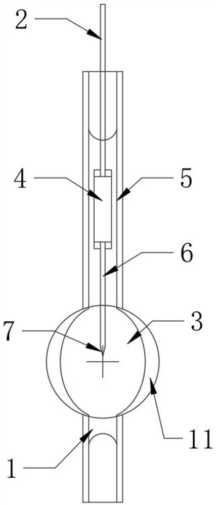
[0028] Embodiment one: refer to figure 1 , a plasma light source cavity for laser maintenance, comprising a quartz cavity 1, an electrode connecting body, and a filling gas in the cavity.
[0029] Quartz cavity 1 is formed of quartz glass material with transmittance not less than 70% in the wavelength range of 170nm to 2300nm, including sealing area 5 and bulb 11; sealing area 5 is a tubular tube communicating with the end of bulb 11 The bulb 11 can be spherical, ellipsoidal, cylindrical, square, rectangular and other shapes suitable for laser pumped plasma, and the inner cavity of the bulb 11 is the ionization cavity 3 . The wall thickness of the middle part of the bulb 11 can be greater than the wall thickness of the end, which can play a role of refraction and help to gather the laser beam.
[0030] An electrode connector for plasma triggering is housed in the quartz chamber 1 for initiating plasma in a given chamber to generate a discharge arc or corona discharge. The el...
Embodiment 2
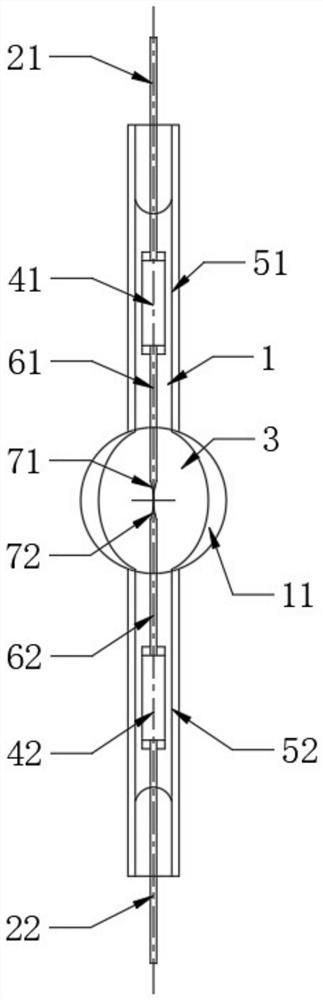
[0038] Embodiment two: refer to figure 2 , a plasma light source cavity for laser maintenance, comprising a quartz cavity 1, two electrode connectors, and filling gas in the cavity.
[0039]The quartz cavity 1 is formed of a quartz glass material with a transmittance not less than 70% in the wavelength range of 170nm to 2300nm, including a first sealing area 51, a second sealing area 52 and a bulb 11; the first sealing area 51 and the second sealing area 52 are both tubular bodies, respectively connected to the two ends of the bulb 11, the bulb 11 can be spherical, ellipsoidal, cylindrical, square, rectangular and other shapes suitable for laser pumped plasma, The inner cavity of bulb 11 is ionization cavity 3 . The wall thickness of the middle part of the bulb 11 can be greater than the wall thickness of the end, which can play a role of refraction and help to gather the laser beam.
[0040] Encapsulate two electrode connectors for plasma triggering in the quartz cavity 1,...
Embodiment 3
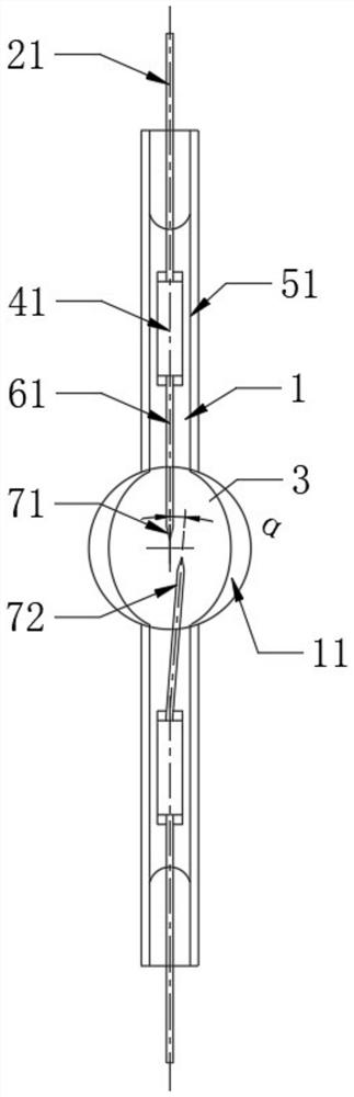
[0048] Embodiment three: refer to image 3 , and the difference from the second embodiment is that the angle between the axes of the first electrode body 61 and the second electrode body 62 is α. α is between 0° and 30°, determined according to product requirements.
[0049] In this way, the tip of the first electrode tip 71 and the second electrode tip 72 are staggered, which can prevent the instantaneous arc from being too strong, and is conducive to maintaining a stable luminous intensity and spectrum under the excitation of the external laser; at the same time, it can reduce the electrode evaporation caused by the transient arc. Phenomenon, prolong the life of the electrode.
[0050] The preparation method of the cavity is the same as that of the second embodiment.
PUM
 Abstract
Description
Claims
Application Information
 - R&D
- Intellectual Property
- Life Sciences
- Materials
- Tech Scout
- Unparalleled Data Quality
- Higher Quality Content
- 60% Fewer Hallucinations
Browse by: Latest US Patents, China's latest patents, Technical Efficacy Thesaurus, Application Domain, Technology Topic, Popular Technical Reports.
© 2025 PatSnap. All rights reserved.Legal|Privacy policy|Modern Slavery Act Transparency Statement|Sitemap|About US| Contact US: help@patsnap.com