Anti-blocking device for blow hole of dip tube of RH furnace and method for removing steel slag from blow hole
A technology of blowing holes and dipping tubes, which is applied in the field of iron and steel metallurgy and steelmaking, which can solve the problems of high cost and long reaction time, and achieve the effects of low cost, short processing time and strong operability
- Summary
- Abstract
- Description
- Claims
- Application Information
AI Technical Summary
Problems solved by technology
Method used
Image
Examples
Embodiment 1
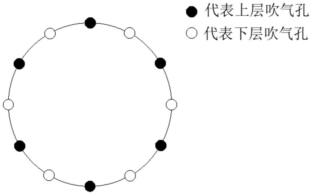
[0028] Such as figure 1 As shown, an anti-blocking device for the blowing hole of the RH furnace dipping tube, including a vacuum tank 1, a dipping tube riser 2, a dipping tube downcomer 3, a blowing hole 4, a nitrogen branch pipe 5, an argon branch pipe 6 and a blowing pipe 7. The bottom of the vacuum tank 1 is provided with a dipping pipe ascending pipe 2 and a dipping pipe descending pipe 3. The lower end of the dipping pipe ascending pipe 2 is provided with a blowing hole 4, and the blowing hole 4 is connected with a blowing pipe 7. Pipeline 7 is connected with a nitrogen sub-pipeline 5 and an argon sub-pipeline 6 from the far-end side of the dipping tube riser 2, and the device also includes an oxygen sub-pipeline 8 and a flow meter 9. The proximal side of 2 is provided with an oxygen sub-pipeline 8 and a flow meter 9 sequentially from left to right.
[0029] The nitrogen sub-pipeline 5, the argon sub-pipeline 6 and the oxygen sub-pipeline 8 are respectively provided wit...
Embodiment 2
[0033] Utilize the anti-clogging device of the RH furnace dipping tube air blowing hole in Example 1 to implement the method of removing the blowing hole steel slag. After the RH furnace smelting is completed, the vacuum tank 1 is repressurized, the operator lowers the ladle, and the blowing hole 4 of the dipping tube ascending pipe 2 is interlocked automatically. Switch from argon to nitrogen protection.
[0034] 1) The pressure of the pressure transmitter corresponding to the nitrogen main pipeline is 1mpa and the initial flow rate of the nitrogen branch pipeline 5 is 85m3 / h. When one of the blowing holes 4 is blocked, the flow value measured by the flow meter 9 is higher than that of the blowing hole 4. The corresponding value of information collection during blockage is reduced by 20%, the pressure value of the pressure transmitter of the oxygen main pipeline is 1.0mpa, and the flow control valve of the corresponding oxygen sub-pipeline 8 is controlled to be opened, and the...
Embodiment 3
[0037] Different from Example 2, when multiple blowing holes 4 are blocked, due to the different degrees of blockage, the change of the required initial oxygen flow rate needs to be considered.
[0038] 1) The pressure of the pressure transmitter corresponding to the nitrogen main pipeline is 1mpa and the initial flow rate of the nitrogen branch pipeline 5 is 85m3 / h. When two of the blowing holes 4 are blocked, the flow value measured by a flowmeter 9 is higher than that of the unblocked one. The corresponding value of information collection is reduced by 25%, and the flow value measured by another flowmeter 9 is 80% lower than the corresponding value of information collection when the blowing hole 4 is not blocked. The pressure value of the pressure transmitter of the oxygen main pipeline is 1.0mpa, and the control is opened The flow control valve of the corresponding oxygen sub-pipeline 8 respectively closes the flow control valve of the nitrogen sub-pipeline 5 after 30 secon...
PUM
 Abstract
Description
Claims
Application Information
 - R&D
- Intellectual Property
- Life Sciences
- Materials
- Tech Scout
- Unparalleled Data Quality
- Higher Quality Content
- 60% Fewer Hallucinations
Browse by: Latest US Patents, China's latest patents, Technical Efficacy Thesaurus, Application Domain, Technology Topic, Popular Technical Reports.
© 2025 PatSnap. All rights reserved.Legal|Privacy policy|Modern Slavery Act Transparency Statement|Sitemap|About US| Contact US: help@patsnap.com


