
Kitchen waste automatic residue discharging and oil separating equipment

A kind of kitchen waste and automatic technology, applied in the direction of presses, manufacturing tools, etc., can solve the problems of poor utilization of waste oil, lack of good recycling devices, machine jamming, etc., to achieve complete functions and structural The effect of compactness and high structural utilization

Active Publication Date: 2021-06-01
张震
View PDF10 Cites 2 Cited by
  • Summary
  • Abstract
  • Description
  • Claims
  • Application Information

AI Technical Summary

Problems solved by technology

[0002] In real life, food waste is often mixed together for treatment, which results in poor utilization of waste oil in food waste, and at the same time, these oils will cause environmental pollution. In order to solve this problem, the application number: CN201820926937.5 discloses an automatic dehydration and slag removal device. This invention is mainly for dehydration of food waste residues. The principle is to separate the solid and liquid through centrifugal stirring, but this is easy to cause sticking to the machine itself, and it does not have relatively good recycling unit

Method used


Image

  • Kitchen waste automatic residue discharging and oil separating equipment
  • Kitchen waste automatic residue discharging and oil separating equipment
  • Kitchen waste automatic residue discharging and oil separating equipment

Examples


Embodiment

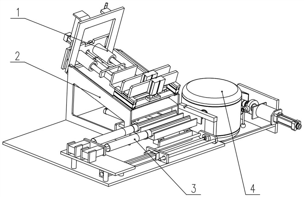
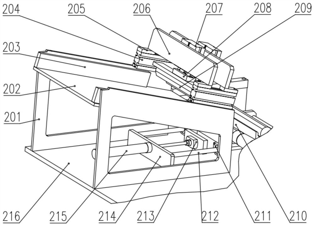
[0022]Example:figure 1 ,figure 2 ,image 3 ,Figure 4 ,Figure 5A kitchen garbage is automatically slag, including a push device 1, a partitioning device 2, a scraping device 3, a fuel supply device 4.

[0023]A specific structure of a kitchen garbage automatic slag gasifer equipment such asfigure 1 As shown in, there is, in which the pusher 1 is fixed to the separator 2, the separator 2 is fixedly mounted on the ground, and the scraping device 3 is fixed to the partitioning device 2, and the oil collecting device 4 is fixedly mounted on the separator 2, will The kitchen waste poured into a kitchen garbage auto-outdrawing oil, in which the partitioning device 2 is used as a primary load-bearing structure, and the pusher 1, the scraping apparatus 3, and the oil supply device 4 are mounted thereon.

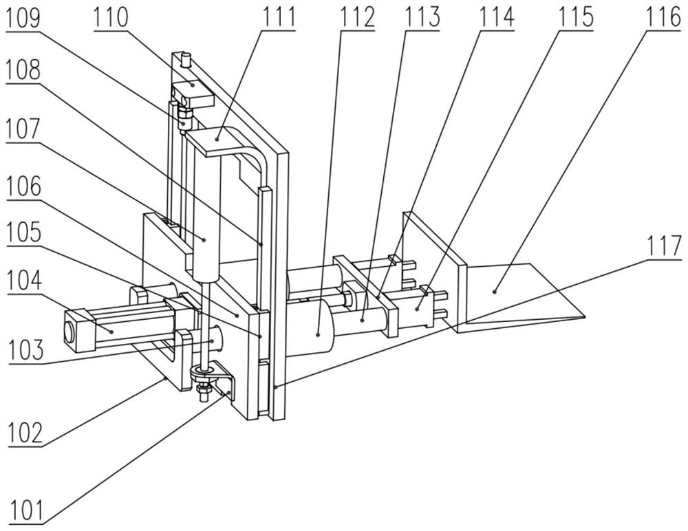
[0024]The specific structure of the pincerization device 1 is likefigure 2 As shown in, the push seat 101 is fixedly mounted on the connecting plate 106, and the pallet 102 is fixed to the support...


PUM


Abstract

The invention discloses kitchen waste automatic residue discharging and oil separating equipment which comprises a pushing device, a separating device, an oil scraping device and an oil collecting device. Kitchen waste is poured into the kitchen waste automatic residue discharging and oil separating equipment, wherein the separating device serves as a main bearing structure, and the pushing device, the oil scraping device and the oil collecting device are fixedly installed on the separating device. A material shoveling plate is driven by a pushing air cylinder on the pushing device to feed in and take back the waste, and a pushing mechanism is driven by a lifting cylinder to ascend and descend. A pressing block is pushed to move through a pressing air cylinder on the separating device, the pressing block can press the kitchen waste to squeeze out oil in the waste, and the oil flows into oil outlet grooves, wherein a position changing air cylinder can drive two oil outlet grooves to change the positions. A piston of an oil scraping air cylinder of the oil scraping device linearly moves in an oil scraping groove along a guide cylinder so as to push the oil into the oil collecting device. The waste oil is collected through an oil barrel of the oil collecting device, and condensed oil blocks in an oil outlet three-way pipe can be cleaned in time through stretching and retracting of a cleaning air cylinder.

Description

Technical field[0001]The present invention relates to the field of industrial machinery, and more particularly to a kitchen garbage automatic slag oil supply equipment.Background technique[0002]In real life, the kitchen garbage often mixed together, so that waste oil in the kitchen garbage does not have better use, and these oil will cause environmental pollution, in order to solve this problem, the application number: CN201820926937.5 An automatic dehydrated slag, which is mainly dehydrated for kitchen waste residue. The principle is to separate the solid-liquid separation by centrifugation, but so that the machine itself is easy to cause the stuck, not with more Good recycling device.Inventive content[0003]TECHNES OF IMPORTECTION OF THE INVENTION The present invention provides a kitchen garbage automatic slag, including a push device, a partitioning device, a scraping apparatus, a fuel supply device, and a push-up device fixedly mounted on a partition device. Fixed mounted on the ...

Claims


Application Information

Patent Timeline
IPC IPC(8): B30B9/04B30B15/30B30B15/32
CPCB30B9/04B30B15/30B30B15/32
Inventor 朱德战
Owner 张震
Learn More