
Cutting machine for hollow wall winding pipe and working method thereof

A winding pipe and cutting machine technology, applied in metal processing and other directions, can solve the problems of uneven pipe cutting end surface, blade jamming, unstable lateral movement speed, etc., achieve the effect of flat cutting port, uniform force, and improved cutting quality

Active Publication Date: 2021-06-01
ANHUI JIELANTE NEW MATERIAL CO LTD
View PDF21 Cites 1 Cited by
  • Summary
  • Abstract
  • Description
  • Claims
  • Application Information

AI Technical Summary

Problems solved by technology

[0003] During the pipe cutting process, the general pipe production only moves laterally. When cutting the pipe, the cutting machine relies on the traction force of the pipe itself to move the chassis forward, but the hollow wall winding pipe moves horizontally in a spiral, and the lateral movement speed is unstable. When cutting the pipe, it relies on the pipe itself. The traction force or fixed setting speed makes the chassis move forward, which is easy to make the end surface of the pipe cutting uneven or the moving speed of the chassis does not match the lateral movement speed of the pipe, causing the blade to be stuck, which has great limitations.

Method used


Image

  • Cutting machine for hollow wall winding pipe and working method thereof
  • Cutting machine for hollow wall winding pipe and working method thereof
  • Cutting machine for hollow wall winding pipe and working method thereof

Examples


Embodiment Construction

[0035] The following will clearly and completely describe the technical solutions in the embodiments of the present invention with reference to the accompanying drawings in the embodiments of the present invention. Obviously, the described embodiments are only some, not all, embodiments of the present invention. Based on the embodiments of the present invention, all other embodiments obtained by persons of ordinary skill in the art without making creative efforts belong to the protection scope of the present invention.

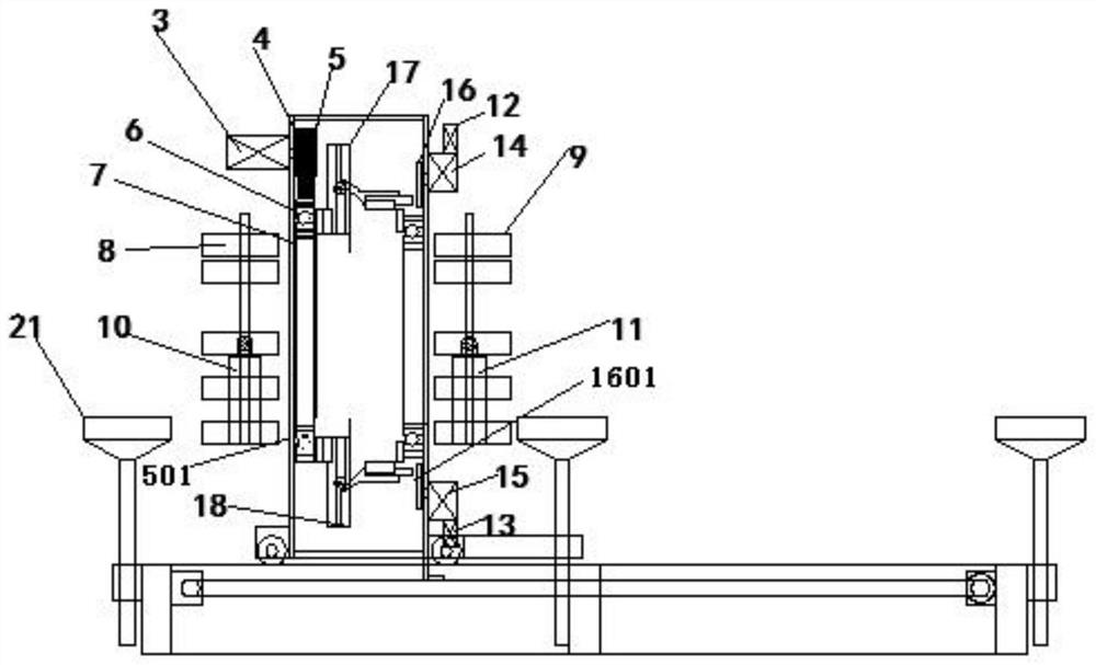
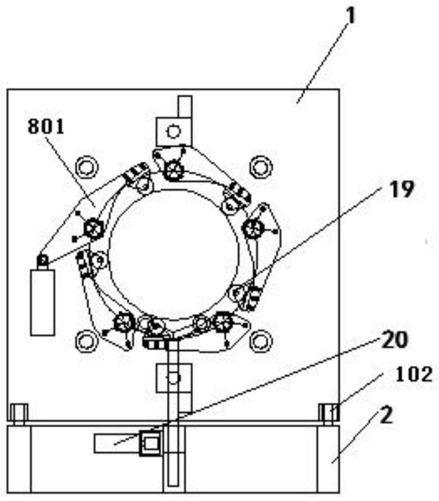
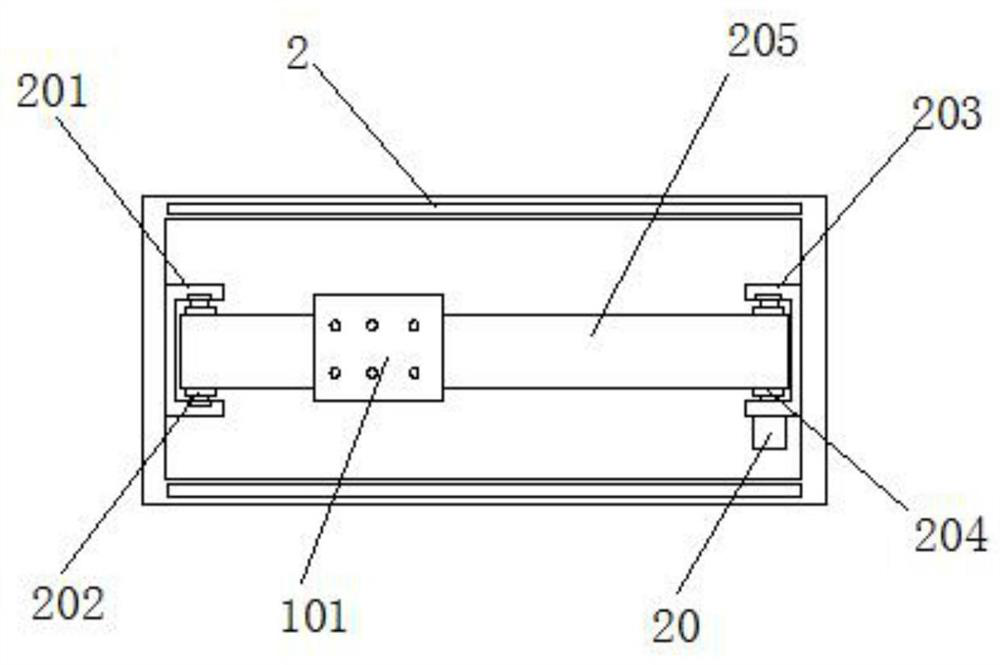
[0036] see Figure 1~6 , in an embodiment of the present invention, a cutting machine for hollow-walled winding pipes includes a casing 1, the fixed mounting of the casing 1 is mounted on a frame 2, and the casing 1 is provided with a through hole for the winding pipe to pass through along the horizontal direction The left side of the chassis 1 and the inlet end of the winding pipe are fixedly provided with a front clamp 8, the right side of the chassis 1 and ...


PUM


Abstract

The invention discloses a cutting machine for a hollow wall winding pipe and a working method thereof. The cutting machine comprises a machine box, a fixed frame of the machine box is arranged on a rack, a through hole allowing the winding pipe to penetrate is formed in the machine box in the horizontal direction, and a front clamp is fixedly arranged at the left side of the machine box and located at the inlet end of the winding pipe; and a rear clamp is fixedly arranged at the right side of the machine box and located at the outlet end of the winding pipe. After the hollow wall winding pipe is formed through a hollow wall winding pipe forming machine, the hollow wall winding pipe is guided into the machine box, a first air cylinder and a second air cylinder drive piston rods to pull clamping blocks on the front clamp and the rear clamp correspondingly, due to the fact that clamp rolling wheels are arranged in the front clamp and the rear clamp, the clamp rolling wheels can transversely clamp the hollow wall winding pipe along with rotation, namely, double-end clamping of the hollow wall winding pipe on the machine box is achieved, cutting of the hollow wall winding pipe on the machine box is more stable, the cutting quality is improved, and the safety performance is good.

Description

technical field [0001] The invention belongs to the technical field of winding pipe processing equipment, and in particular relates to a hollow-wall winding pipe cutting machine and a working method thereof. Background technique [0002] The coiled hose is a new product that replaces the traditional metal spring for rubber hose protection. The winding tube is generally made of nylon or polypropylene. Corresponding to the traditional metal spring protection products, the winding tube has good wear resistance, strong anti-aging and corrosion resistance; it can more effectively protect the outer surface of the hose against aging and anti-friction. Compared with rubber hose protection spring products and other sheath products, the winding pipe has more excellent convenience, environmental protection and energy saving effect. The inner surface of the winding tube is generally flat, and the outer surface is divided into two types: flat and curved. The plastic-steel winding pipe...

Claims


Application Information

Patent Timeline
Patent Type & Authority Applications(China)
IPC IPC(8): B26D1/09B26D5/08B26D7/02B26D7/26
CPCB26D1/09B26D5/086B26D7/02B26D7/2628B26D2007/013
Inventor 刘俊峰刘文江万刚田祥军曹操姜繁张俊
Owner ANHUI JIELANTE NEW MATERIAL CO LTD
Learn More