
Auxiliary switching device for multifunctional lathe tool bit fixing frame

A switching device and a fixed frame technology, applied in the field of lathes, can solve problems such as inability to guarantee the accuracy of tool installation, damage to the lathe, and influence on lathe processing, so as to improve automation level and practicability, ensure stability and reliability, improve quality and The effect of precision

Inactive Publication Date: 2021-06-01
高红莉
View PDF0 Cites 0 Cited by
  • Summary
  • Abstract
  • Description
  • Claims
  • Application Information

AI Technical Summary

Problems solved by technology

[0005] Aiming at the deficiencies of the prior art, the present invention provides an auxiliary switching device for a multifunctional lathe tool head fixing frame, which has the advantages of fast positioning, automatic clamping, high precision, high efficiency, and reduced workload of operators, and solves the problem of existing problems. The clamping mechanism of some lathe tools is generally clamped manually through fixed parts such as screw rods. This makes the positioning of the tool greatly affected by human operation, and at the same time makes the installation process of the tool time-consuming and laborious and cannot guarantee the tool. The installation accuracy will also have a certain impact on the machining of the lathe. Inaccurate positioning of the tool and insufficient clamping force will seriously affect the running stability of the lathe and even damage the lathe.

Method used


Image

  • Auxiliary switching device for multifunctional lathe tool bit fixing frame
  • Auxiliary switching device for multifunctional lathe tool bit fixing frame
  • Auxiliary switching device for multifunctional lathe tool bit fixing frame

Examples


Embodiment Construction

[0025] The following will clearly and completely describe the technical solutions in the embodiments of the present invention with reference to the accompanying drawings in the embodiments of the present invention. Obviously, the described embodiments are only some, not all, embodiments of the present invention. Based on the embodiments of the present invention, all other embodiments obtained by persons of ordinary skill in the art without making creative efforts belong to the protection scope of the present invention.

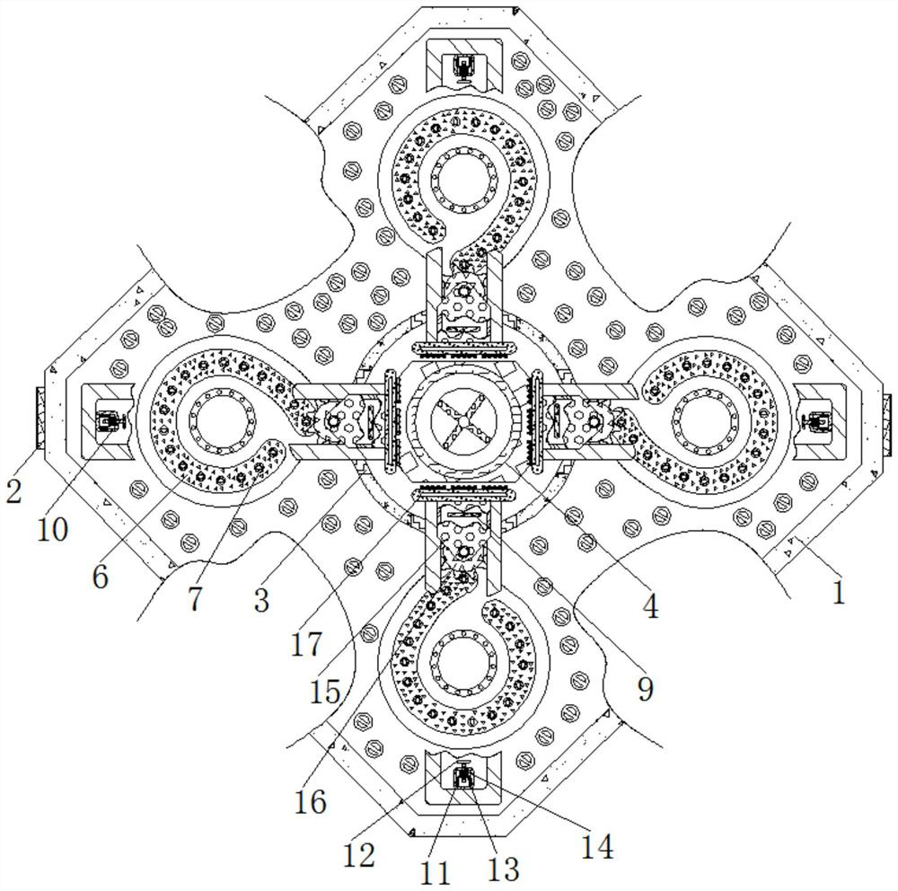
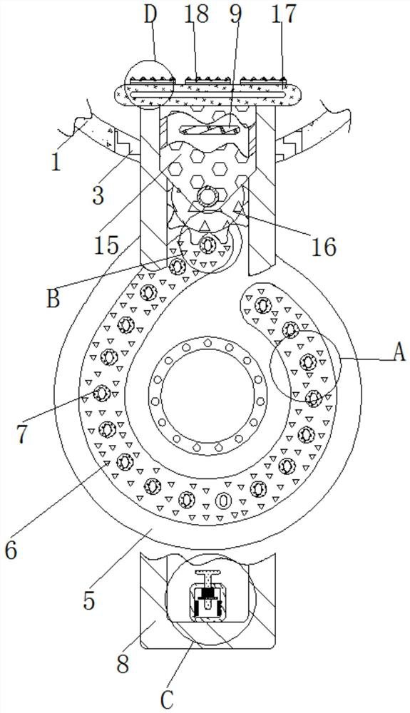
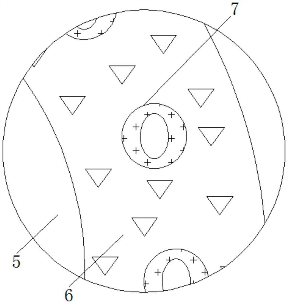
[0026] see Figure 1-6 , an auxiliary switching device for a multifunctional lathe tool head holder, comprising a housing 1, a button 2 is fixedly connected to the outside of the housing 1, an outlet 3 is provided on the surface of the housing 1, a weight-reducing port is provided on the surface of the housing 1, and the weight-reducing port The number of them is not less than twenty, all the weight reducing ports are evenly distributed on the surface of the s...


PUM


Abstract

The invention relates to the technical field of lathes, and discloses a auxiliary switching device for a multifunctional lathe tool bit fixing frame. The auxiliary switching device for the multifunctional lathe tool bit fixing frame comprises a shell, a button is fixedly connected to the exterior of the shell, an outlet is formed in the surface of the shell, a clamping plate is fixedly connected to the exterior of the shell, a rotating plate is movably connected to the interior of the shell, a groove is formed in the surface of the rotating plate, and the inner side of the groove is fixedly connected with a transmission shaft. Under the interaction of the outlet, the clamping plate, the rotating plate, the groove, the transmission shaft, a sliding rail, a touch plate, a protection cover, a charge polar plate, an insulating plate, a dielectric medium plate, a spring, a sliding block, a rotating wheel, a supporting plate and a fastening plate, the working efficiency of installing a tool by an operator can be remarkably improved, meanwhile, the situation that normal operation of a lathe is affected or even the lathe is damaged due to the fact that the tool is not installed in place is avoided, the quality and precision of parts machined by the lathe are improved, and the automation level and practicability of the lathe are improved.

Description

technical field [0001] The invention relates to the technical field of lathes, in particular to an auxiliary switching device for a tool head fixing frame of a multifunctional lathe. Background technique [0002] A lathe is a machine tool that mainly uses a turning tool to turn a rotating workpiece. Drills, reamers, reamers, taps, dies, and knurling tools can also be used on the lathe for corresponding processing. The lathe is divided into spindle boxes according to the structure. , feed box, lead screw and feed rod, sliding crate, tool holder, bed, etc., the clamping mechanism of the existing lathe tool is generally manually clamped through fixed parts such as screw rods, so that the tool The positioning of the tool is greatly affected by human operation. At the same time, the installation process of the tool is time-consuming and laborious, and the installation accuracy of the tool cannot be guaranteed, which will also have a certain impact on the processing of the lathe. ...

Claims


Application Information

Patent Timeline
Patent Type & Authority Applications(China)
IPC IPC(8): B23B29/04
CPCB23B29/04
Inventor 高红莉
Owner 高红莉
Learn More