Double-layer wall cap anti-icing system with impact-gas film structure on front edge

An anti-icing system and cap technology, which are applied in jet propulsion devices, gas turbine devices, machines/engines, etc., can solve the problem that the internal heat exchange of the impact heat exchange structure is limited, the anti-icing measures outside the cap are not considered, and it is difficult to achieve anti-icing. effect and other issues, so as to meet the processing requirements, improve the implementability of processing, and enhance the anti-icing effect.

Pending Publication Date: 2021-05-28
NORTHWESTERN POLYTECHNICAL UNIV
View PDF1 Cites 0 Cited by
  • Summary
  • Abstract
  • Description
  • Claims
  • Application Information

AI Technical Summary

Problems solved by technology

[0006] Aiming at the icing problem at the front edge of the hood, this structure introduces an impact heat transfer structure to enhance the internal heat transfer of the wall at the front edge of the hood and improve the heat transfer effect of the front edge, but does not consider the external anti-icing of the hood Measures, only take certain measures to enhance the internal heat transfer effect, resulting in a certain temperature gradient on the wall surface of the cap, resulting in a certain thermal stress and reducing its fatigue life; and the internal heat transfer of the impact heat transfer structure is limited, Difficult to achieve better anti-icing effect

Method used


Image

  • Double-layer wall cap anti-icing system with impact-gas film structure on front edge
  • Double-layer wall cap anti-icing system with impact-gas film structure on front edge
  • Double-layer wall cap anti-icing system with impact-gas film structure on front edge

Examples


Embodiment Construction

[0027] The embodiments described below by referring to the figures are exemplary and are intended to explain the present invention and should not be construed as limiting the present invention.

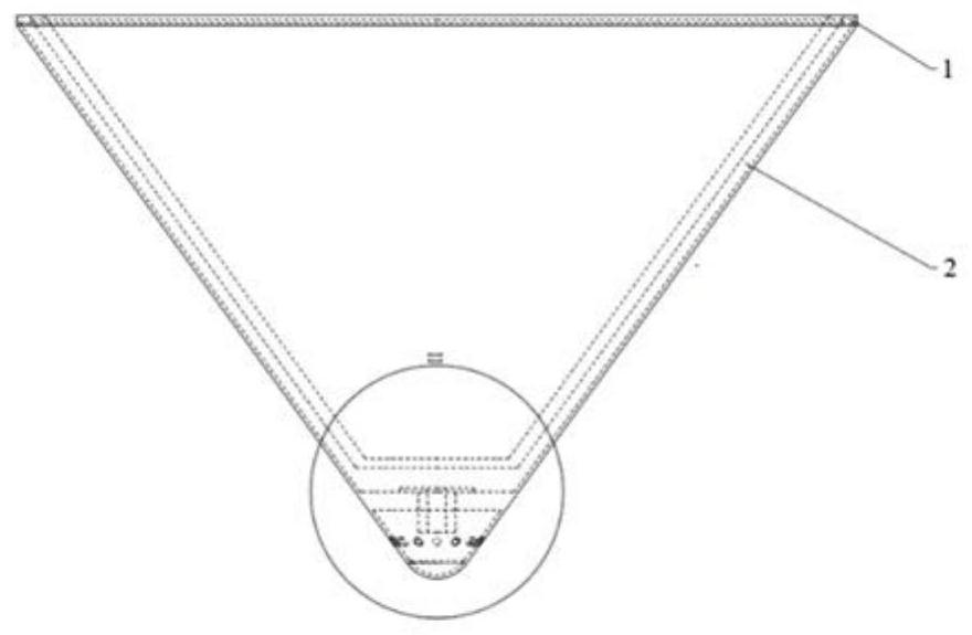
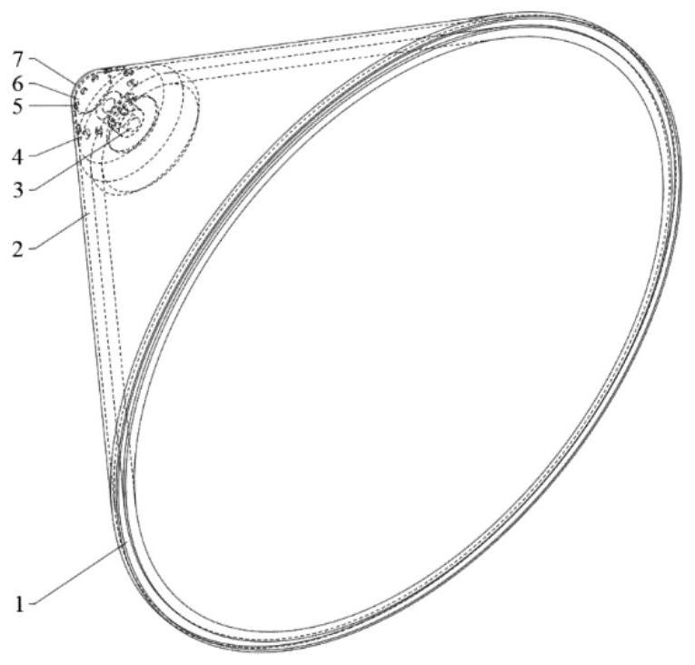
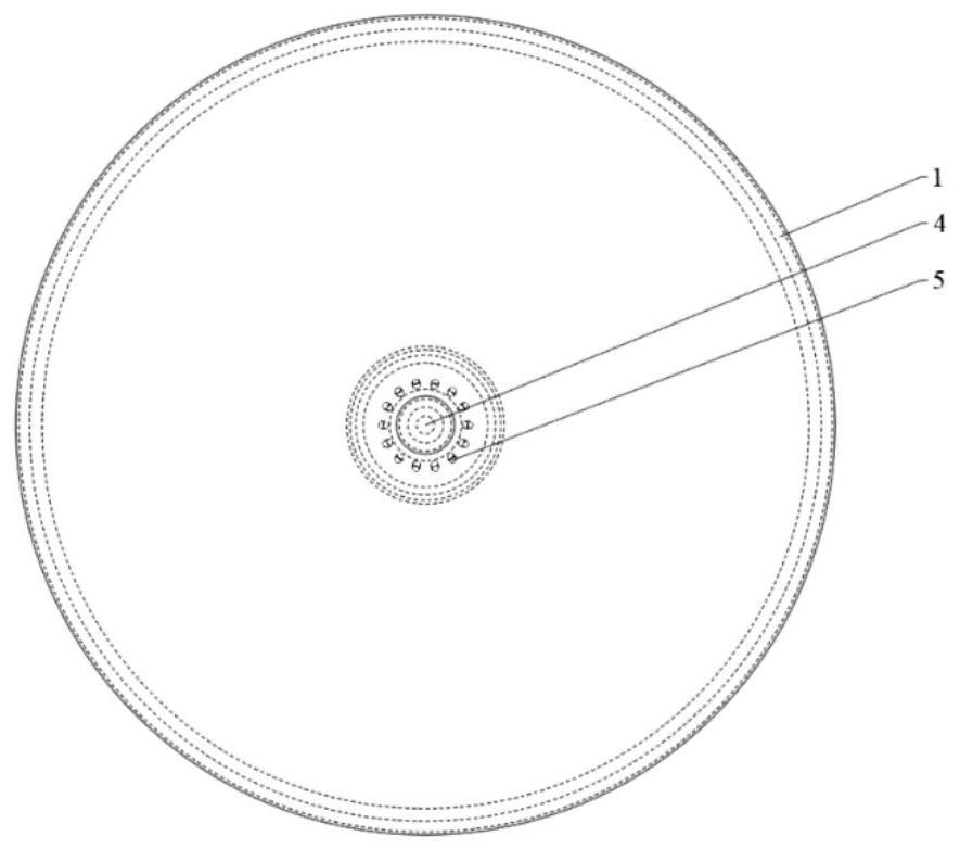
[0028] refer to Figure 1 to Figure 5 , this implementation is a double-wall cowl anti-icing system with an impact-gas film structure on the front edge, which is applied to the front edge impact area of ​​the aero-engine cowling, consisting of hot gas inlet 1, hot gas channel 2, and impact orifice plate 3. The impact hole 4, the air film hole 5, the inner chamber 6 impacted by the front edge of the cap, and the wall surface 7 at the front edge of the cap. A row of cylindrical air film holes is arranged at the front edge of the cap, and the hot gas enters the front edge of the cap through the impact holes to impact the inner cavity, and after impact heat exchange and convective heat exchange with the front edge of the cap, it flows out from the air film holes and the cap heat exchange...


PUM


Abstract

The invention discloses a double-layer wall cap anti-icing system with an impact-gas film structure on the front edge, and belongs to the technical field of aero-engine cap anti-icing. The double-layer wall cap anti-icing system comprises a cap inner wall surface, a cap outer wall surface and an impact hole plate, and an annular gap between the cap inner wall surface and the cap outer wall surface forms a hot gas channel; an impact hole is formed in the center of the impact hole plate, and a cavity between the impact hole and the front edge wall surface of a cap is a front edge impact inner cavity of the cap; a plurality of gas film holes are evenly distributed in the front edge wall surface of the cap in the circumferential direction, the included angle between the center axis of each gas film hole and the center axis of the cap is 90 degrees, and the holes are cylindrical holes; the distance between the plane where the multiple gas film holes are located and the rounding face of the front edge of the cap is L, and the ratio of the distance to the diameter D of the impact hole is 1.2-2.4; and hot gas flows into the hot gas channel from a hot gas inlet, enters the front edge impact inner cavity of the cap through the impact hole in the impact hole plate after performing heat convection with the cap inner wall surface, then performs impact heat exchange and heat convection with the front edge of the cap, and finally flows out of the gas film holes to exchange heat with the cap outer wall surface.

Description

technical field [0001] The invention belongs to the technical field of anti-icing technology of aero-engine caps, and in particular relates to a double-wall cap anti-icing system with an impact-air film structure on the leading edge. Background technique [0002] The icing of the air intake system of an aeroengine will seriously affect the normal operation of the engine and seriously endanger the flight safety of the aircraft. When the aircraft passes through the low-temperature atmospheric cloud layer, the supercooled water droplets, ice crystals, freezing rain and snowfall in the air will cause damage to many parts such as the leading edge of the wing and empennage, the windshield, the leading edge of the air inlet and the engine intake parts (support panels, fairings, etc.) to form icing phenomena. Therefore, it is necessary to implement better anti-icing measures for the imported parts of the engine to suppress the phenomenon of icing. The generation of ice accumulatio...

Claims


Application Information

Patent Timeline
Patent Type & Authority Applications(China)
IPC IPC(8): F02C7/047
CPCF02C7/047
Inventor 许卫疆李洁博郭奕杉苏博
Owner NORTHWESTERN POLYTECHNICAL UNIV
Why Eureka
Try Eureka