A microwave electrodeless ultraviolet lamp device
A UV lamp and microwave technology, applied in the microwave field, can solve the problems of insufficient compact size, space occupation, and low power, and achieve the effects of reducing microwave leakage, high work efficiency, and compact structure
- Summary
- Abstract
- Description
- Claims
- Application Information
AI Technical Summary
Problems solved by technology
Method used
Image


Examples
Embodiment 1
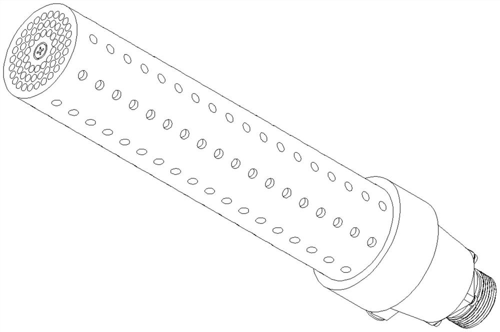
[0022] See attached Figure 1~3 . A microwave electrodeless ultraviolet lamp device, comprising a radiation rod 1, a metal mesh cover 2 and a lamp body 3; the metal mesh cover 2 is covered with a lamp body 3; the lamp body 3 is covered with a radiation rod 1; the lamp The body 3 includes an inner wall layer 4 and an outer wall layer 5; an interlayer 6 is provided between the inner wall layer 4 and the outer wall layer 5; a filler is sealed in the interlayer 6; Microwaves are fed into space 7 . It can be seen from the above structure that the radiation rod 1, the metal mesh cover 2 and the lamp body 3 extend coaxially, and the microwave enters the microwave feeding space 7 from the front end of the microwave feeding space 7, and the radiation rod 1 and the metal mesh cover 2 are in the same group The coaxial waveguide enables the microwave to be transmitted axially, and the microwave fully penetrates the inner wall layer 4 to fully excite the filler in the interlayer 6 to rad...
Embodiment 2
[0024] See attached Figure 1~3 . A microwave electrodeless ultraviolet lamp device, comprising a radiation rod 1, a metal mesh cover 2 and a lamp body 3; the metal mesh cover 2 is covered with a lamp body 3; the lamp body 3 is covered with a radiation rod 1; the lamp The body 3 includes an inner wall layer 4 and an outer wall layer 5; an interlayer 6 is provided between the inner wall layer 4 and the outer wall layer 5; a filler is sealed in the interlayer 6; Microwaves are fed into space 7 . It can be seen from the above structure that the radiation rod 1, the metal mesh cover 2 and the lamp body 3 extend coaxially, and the microwave enters the microwave feeding space 7 from the front end of the microwave feeding space 7, and the radiation rod 1 and the metal mesh cover 2 are in the same group The coaxial waveguide enables the microwave to be transmitted axially, and the microwave fully penetrates the inner wall layer 4 to fully excite the filler in the interlayer 6 to radia...
Embodiment 3
[0030] See attached Figure 4 . A microwave electrodeless ultraviolet lamp device, comprising a radiation rod 1, a metal mesh cover 2 and a lamp body 3; the metal mesh cover 2 is covered with a lamp body 3; the lamp body 3 is covered with a radiation rod 1; the lamp The body 3 includes an inner wall layer 4 and an outer wall layer 5; an interlayer 6 is provided between the inner wall layer 4 and the outer wall layer 5; a filler is sealed in the interlayer 6; Microwaves are fed into space 7 . It can be seen from the above structure that the radiation rod 1, the metal mesh cover 2 and the lamp body 3 extend coaxially, and the microwave enters the microwave feeding space 7 from the front end of the microwave feeding space 7, and the radiation rod 1 and the metal mesh cover 2 are in the same group The coaxial waveguide enables the microwave to be transmitted axially, and the microwave fully penetrates the inner wall layer 4 to fully excite the filler in the interlayer 6 to radia...
PUM
 Abstract
Description
Claims
Application Information
 - R&D
- Intellectual Property
- Life Sciences
- Materials
- Tech Scout
- Unparalleled Data Quality
- Higher Quality Content
- 60% Fewer Hallucinations
Browse by: Latest US Patents, China's latest patents, Technical Efficacy Thesaurus, Application Domain, Technology Topic, Popular Technical Reports.
© 2025 PatSnap. All rights reserved.Legal|Privacy policy|Modern Slavery Act Transparency Statement|Sitemap|About US| Contact US: help@patsnap.com