
A Cylindrical Grinding Device for Hydraulic Compensation Valve Core

A technology of processing device and compensation valve, which is applied in metal processing equipment, grinding workpiece supports, manufacturing tools, etc., can solve the problem of small external tolerance of hydraulic compensation valve core, placement of hydraulic compensation valve core, and reduce the safety of cylindrical grinding processing device. problems such as performance and effect, to improve processing efficiency and avoid wear and tear

Active Publication Date: 2022-05-03
WUXI YINGBEI PRECISION BEARING
View PDF0 Cites 0 Cited by
  • Summary
  • Abstract
  • Description
  • Claims
  • Application Information

AI Technical Summary

Problems solved by technology

[0003] When the current cylindrical grinding machine performs cylindrical grinding on the hydraulic compensation valve core, due to the small tolerance of the hydraulic compensation valve core, the equipment debugging time is long, the processing is single-piece processing, the efficiency is low, and the processing size is unstable, thereby greatly reducing the cost. The efficiency of the device for grinding the hydraulic compensation spool is improved; and the current cylindrical grinding machine usually needs to wait until the first set of hydraulic compensation spool is processed and removed before the next set of hydraulic compensation spool can be placed. Grinding on the cylindrical grinding machine, during the replacement of parts, the entire cylindrical grinding machine is in a state of stopping processing, which further reduces the processing efficiency of the cylindrical grinding machine; at the same time, when the current cylindrical grinding machine replaces parts, the operator needs to manually The hydraulic compensation spool is placed on the grinding part of the cylindrical grinder. During the process, the rotating components of the cylindrical grinder can easily cause damage to the operator's hands, and the hydraulic compensation spool cannot be placed smoothly on the grinding machine. position, thus greatly reducing the safety and effectiveness of the entire cylindrical grinding device

Method used


Image

  • A Cylindrical Grinding Device for Hydraulic Compensation Valve Core
  • A Cylindrical Grinding Device for Hydraulic Compensation Valve Core
  • A Cylindrical Grinding Device for Hydraulic Compensation Valve Core

Examples


Embodiment 1

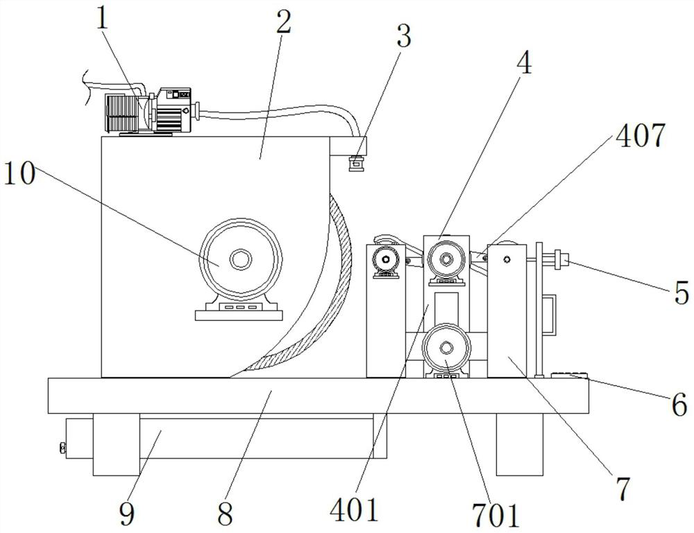
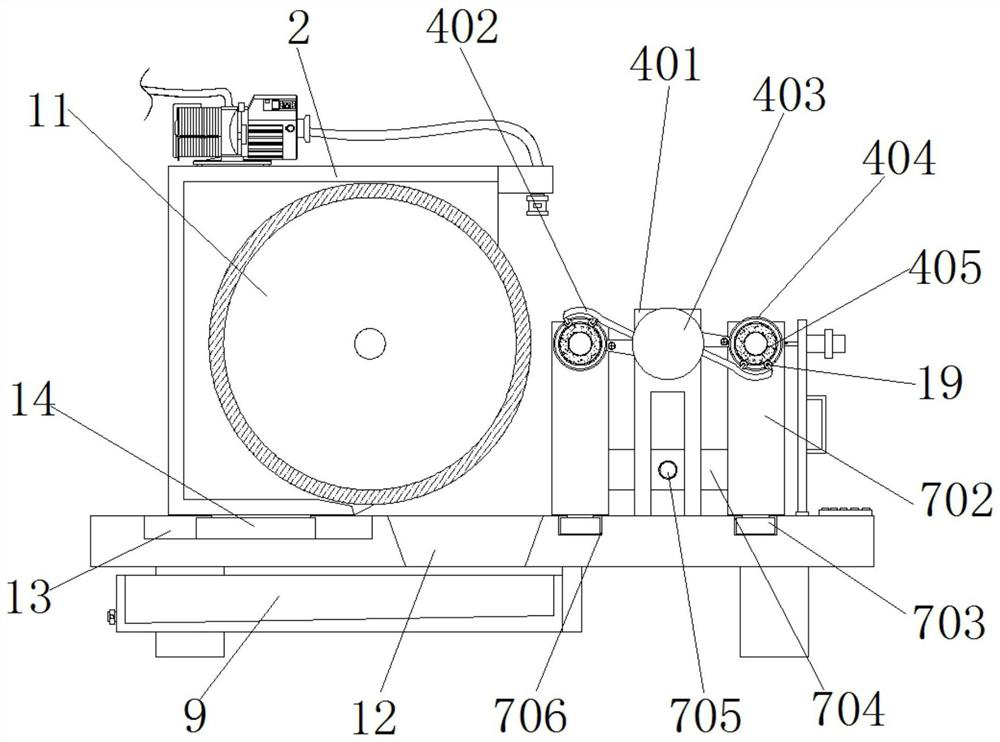
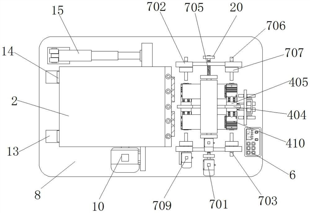
[0033] Example 1, such as figure 1 , 2 , 3, 4, 5 and 7, when replacing a new hydraulic compensating spool 410, when the hydraulic compensating spool 410 at both ends of a set of grinding jacket 405 has been ground, the first servo motor 406 drives the guide The roller 403 rotates 180° clockwise, so that the next set of fixed grinding jacket 405 and hydraulic compensation valve core 410 rotate to the position close to the grinding wheel 11, and the two sets of hydraulic compensation valve cores 410 that have been ground Then turn to the end away from the grinding wheel 11, the operator manually turns the threaded hole 409 on the set of grinding jacket 405 to face the electric screwdriver 5, and then loosens the screw 408 through the electric screwdriver 5, and then controls the second servo motor 701 to reverse Rotate to make the two groups of horizontal plates 704 away from each other, which also makes the splint 707 away from each other, so that the hydraulic compensation va...

Embodiment 2

[0034] Example 2, such as Figure 1-7 As shown, when processing the hydraulic compensation spool 410, the third servo motor 709 is controlled to rotate in the same direction as the grinding wheel 11, and the third servo motor 709 drives the connected splint 707 to drive the connected two sets of hydraulic compensation spools 410 and The grinding jacket 405 rotates in the same direction synchronously, and then the electric push rod 15 is controlled to push the installation chamber 2 to move, so that the surface of the grinding wheel 11 is in contact with the surface of the hydraulic compensation spool 410 , and the surface of the hydraulic compensation spool 410 is ground.

[0035] Working principle: connect the device to the power supply before use, first place the same ends of the two sets of hydraulic compensating spools 410 on the two sets of rollers on the top of a set of arc-shaped plates 402, and then control the second servo motor 701 through the control panel 6 Forward...


PUM


Abstract

The invention discloses a cylindrical grinding device for a hydraulic compensating valve core, which comprises a mounting platform, a second chute is symmetrically opened on both sides of one end of the top of the mounting platform, and a second chute is arranged inside the second chute. slider, and the tops of the two groups of second sliders are jointly installed with installation bins, the inner two sides of the installation bins are jointly provided with grinding wheels, one side of the installation bins is equipped with a drive motor, and the output end of the drive motor It is connected with the drive on one side of the grinding wheel. In the present invention, the push plate, the grinding jacket, the screw, the threaded hole and the hydraulic compensating valve core are used together, the screws are tightened by two sets of electric screwdrivers, and the two sets of hydraulic compensating valve cores are fixed on both ends of the grinding jacket by the screws. It can not only grind the two sets of hydraulic compensation spools at the same time, improve the processing efficiency of the device, but also ensure that the two sets of hydraulic compensation spools can be more stable during the grinding process, avoiding the phenomenon of abrasion on the surface of the hydraulic compensation spools during processing .

Description

technical field [0001] The invention relates to the technical field of mechanical manufacturing, in particular to a cylindrical grinding device for a hydraulic compensation valve core. Background technique [0002] Hydraulic motors, also known as oil motors, are mainly used in injection molding machinery, ships, hoists, construction machinery, construction machinery, coal mining machinery, mining machinery, metallurgical machinery, ship machinery, etc., and the hydraulic compensation spool is an important part of the motor power system. Accessories, the heat-treated hydraulic compensating spool has the advantages of high hardness and good wear resistance. In the hydraulic motor, can the power of the hydraulic motor be realized by accurately controlling the flow rate. [0003] When the current cylindrical grinding machine performs cylindrical grinding on the hydraulic compensation valve core, due to the small tolerance of the hydraulic compensation valve core, the equipment d...

Claims


Application Information

Patent Timeline
Patent Type & Authority Patents(China)
IPC IPC(8): B24B41/06B24B41/00
CPCB24B41/06B24B41/00
Inventor 陈铭佳冯贇
Owner WUXI YINGBEI PRECISION BEARING
Learn More