Electronic gas tail gas intelligent recovery device and method

An electronic gas and recovery device technology, applied in separation methods, chemical instruments and methods, and dispersed particle separation, can solve problems such as high equipment cost, gas leakage, and environmental protection, and achieve efficient water washing and efficient treatment.

Active Publication Date: 2021-05-25
铜陵安德科铭电子材料科技有限公司
View PDF4 Cites 2 Cited by
  • Summary
  • Abstract
  • Description
  • Claims
  • Application Information

AI Technical Summary

Problems solved by technology

[0002] Electronic gas is an indispensable basic supporting raw material in the development of integrated circuits, optoelectronics, microelectronics, especially VLSI, liquid crystal display devices, semiconductor light-emitting devices and semiconductor materials. It is called the "blood" of the electronics industry And "food", its purity and cleanliness directly affect the quality, integration, specific technical indicators and yield of optoelectronics and microelectronic components, and fundamentally restrict the precision and accuracy of circuits and devices. Whether the gas is used as a cleaning agent or an etchant, the utilization rate is only 30-70%, so the electron gas tail gas contains a large amount of unused electron gas and the (C-H)n polymer generated during the cleaning and etching process, and most of the electron gas is Greenhouse gas is the largest source of greenhouse gas emissions in the semiconductor industry: electronic gas tail gas emissions not only cause waste of electronic gases but also affect environmental protection
[0003] Existing electronic gas tail gas recovery devices are generally directly equipped with multiple spray towers to remove impurities in the gas through continuous spraying of the gas, resulting in numerous operating procedures, high equipment costs, cumbersome operations, and low recovery efficiency. Moreover, it is easy to cause gas leakage during multiple operating procedures, which affects the recovery effect of gas. Therefore, we propose an electronic gas tail gas intelligent recovery device and method

Method used


Image

  • Electronic gas tail gas intelligent recovery device and method
  • Electronic gas tail gas intelligent recovery device and method
  • Electronic gas tail gas intelligent recovery device and method

Examples


Embodiment Construction

[0031] The following will clearly and completely describe the technical solutions in the embodiments of the present invention with reference to the accompanying drawings in the embodiments of the present invention. Obviously, the described embodiments are only some, not all, embodiments of the present invention. Based on the embodiments of the present invention, all other embodiments obtained by persons of ordinary skill in the art without making creative efforts belong to the protection scope of the present invention.

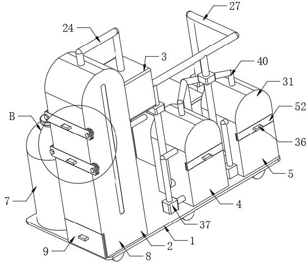
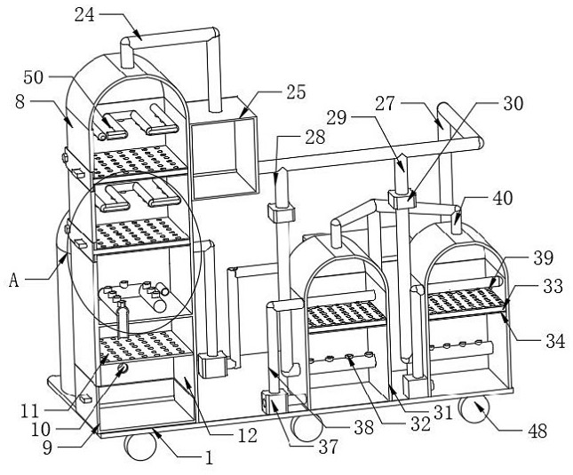
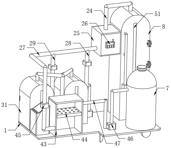
[0032] see figure 1 , Figure 6 and Figure 8 , the present invention provides a technical solution: an electronic gas tail gas intelligent recovery device, including a substrate 1 and a console 49, one end of the top of the substrate 1 is provided with a console 49, and also includes: a first processing mechanism 2, a detection mechanism 3. The second processing mechanism 4, the third processing mechanism 5, the gas dehumidification mechanism 6, the electro...


PUM


Abstract

The invention relates to the technical field of electronic gas tail gas recovery, and particularly relates to an intelligent electronic gas tail gas recovery device and method. The device comprises a base plate and a console, wherein the console is arranged at one end of the top of the base plate. The device further comprises a first processing mechanism, a detection mechanism, a second processing mechanism, a third processing mechanism, a gas dehumidification mechanism and an electronic gas collection tank, wherein the first processing mechanism is arranged at the other end of the top of the base plate, the second processing mechanism and the third processing mechanism are arranged at the top of the base plate and located on one side of the console, the gas dehumidification mechanism is arranged at the top of the base plate and located on the other side of the console, the electronic gas collection tank is installed at the top of the base plate and located on the side edge of the first processing mechanism, and the first processing mechanism comprises a first processing box. The device is compact in structure, continuous in operation, convenient to move, cost-saving and high in recovery efficiency.

Description

technical field [0001] The invention relates to the technical field of electronic gas tail gas recovery technology, in particular to an electronic gas tail gas intelligent recovery device and method. Background technique [0002] Electronic gas is an indispensable basic supporting raw material in the development of integrated circuits, optoelectronics, microelectronics, especially VLSI, liquid crystal display devices, semiconductor light-emitting devices and semiconductor materials. It is called the "blood" of the electronics industry And "food", its purity and cleanliness directly affect the quality, integration, specific technical indicators and yield of optoelectronics and microelectronic components, and fundamentally restrict the precision and accuracy of circuits and devices. Whether the gas is used as a cleaning agent or an etchant, the utilization rate is only 30-70%, so the electron gas tail gas contains a large amount of unused electron gas and the (C-H)n polymer ge...

Claims


Application Information

Patent Timeline
Patent Type & Authority Applications(China)
IPC IPC(8): B01D46/10B01D53/78B01D53/40B01D53/42B01D53/26
CPCB01D46/10B01D53/78B01D53/42B01D53/40B01D53/261
Inventor 汪海燕林素贞刘振宇
Owner 铜陵安德科铭电子材料科技有限公司
Why Eureka
Try Eureka