
Environment-friendly grinding device

An environmental protection and grinding mechanism technology, applied in the direction of grinding drive device, grinding/polishing safety device, grinding machine, etc., can solve the problems of affecting the appearance, multiple grooves on the wall, and cleaning of broken stones, etc.

Inactive Publication Date: 2021-05-18
赵月凤
View PDF6 Cites 1 Cited by
  • Summary
  • Abstract
  • Description
  • Claims
  • Application Information

AI Technical Summary

Problems solved by technology

[0003] With the rapid development of science and technology in our country, generations of grinding machines are gradually coming out, which mainly include large grinding machines and small grinding machines. For the grinding of concrete floors, large grinding machines are usually used for grinding, and its efficiency is undoubtedly greatly increased. However, Grinding of concrete walls is usually accomplished by hand-held small grinders. Since there are many crushed stones mixed in the concrete, although the commonly used plane hand-held grinders can achieve the grinding of the walls, they cannot grind the concrete. The broken stones in the wall are cleaned, resulting in a lot of broken stones inlaid on the wall after the grinding is completed. These broken stones need to be removed manually after the grinding is completed. After the removal, it will not only affect the appearance, but also make the wall appear More grooves affect the structural strength of the wall

Method used


Image

  • Environment-friendly grinding device
  • Environment-friendly grinding device
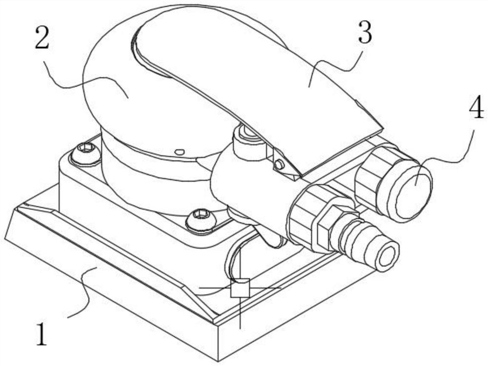
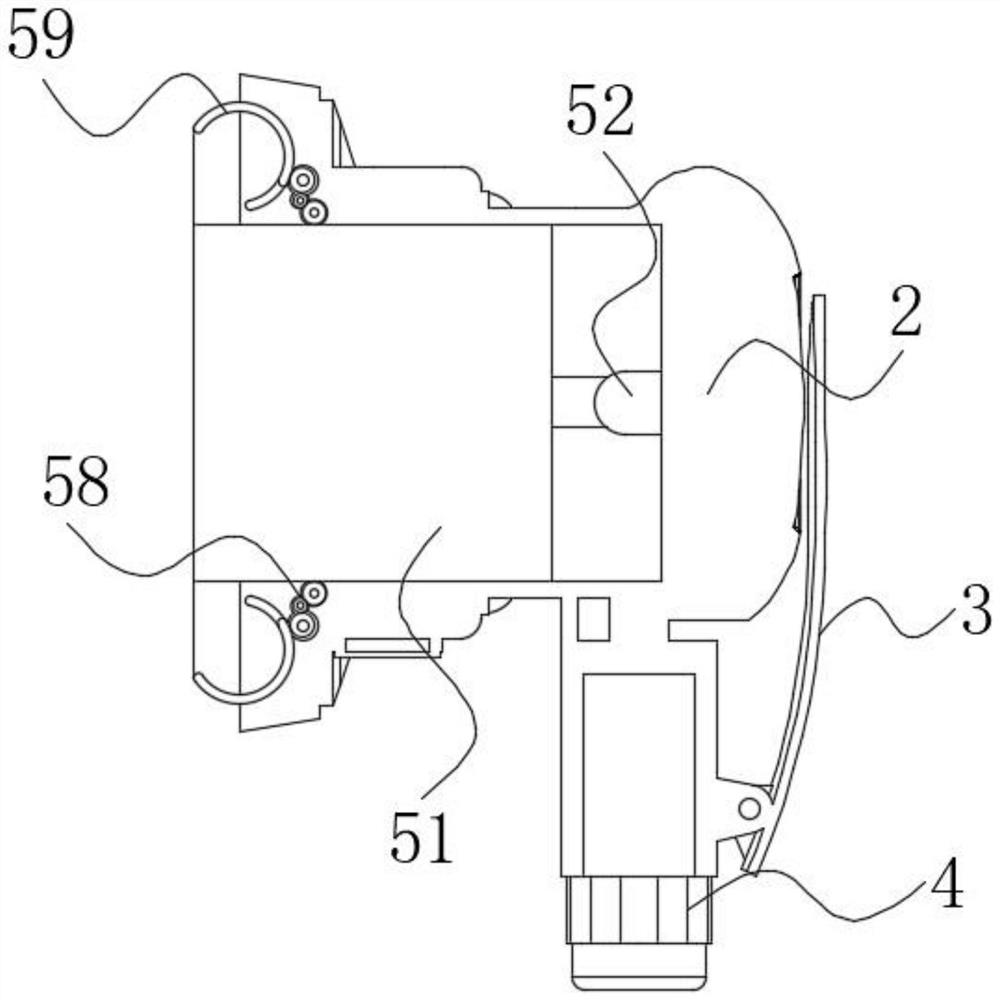
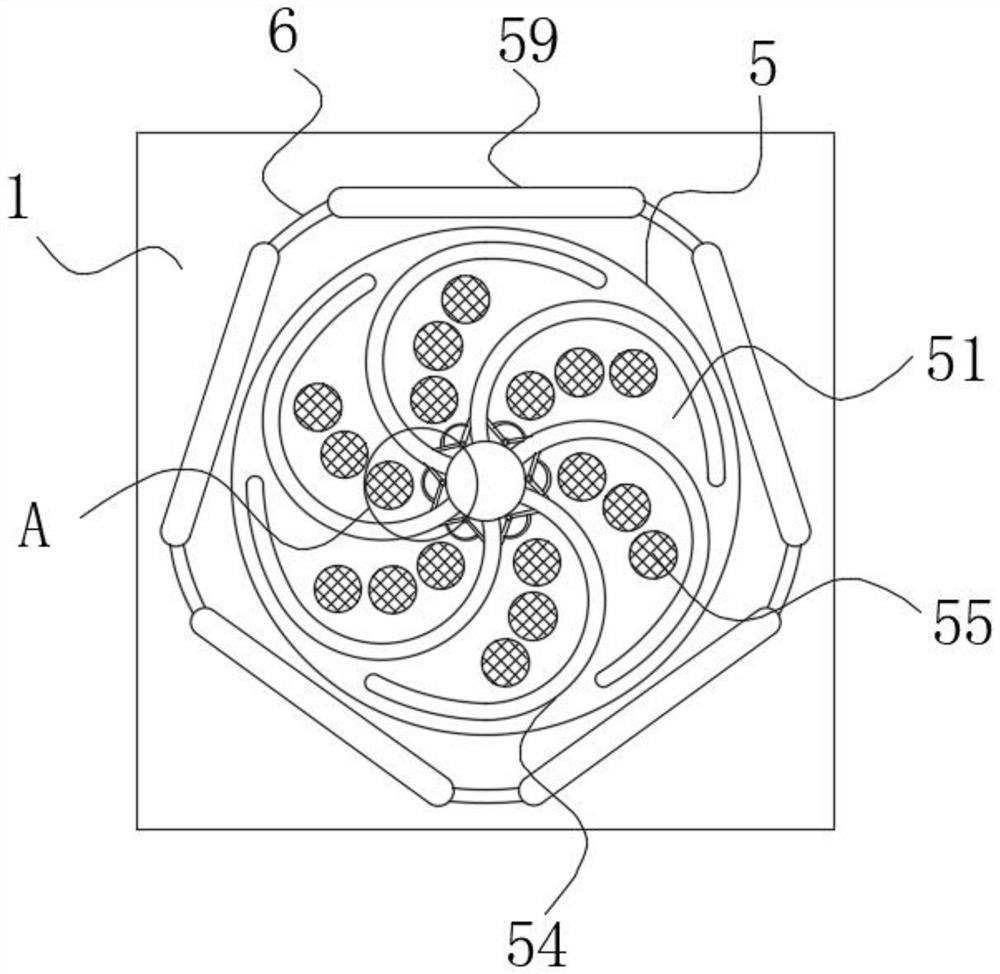
  • Environment-friendly grinding device

Examples


Embodiment Construction

[0022] use Figure 1-Figure 6 An environmentally friendly grinding device according to an embodiment of the present invention will be described as follows.

[0023] Such as Figure 1-Figure 6As shown, a kind of environmental protection polishing device described in the present invention comprises installation block 1, motor 2, handle 3, suction joint 4 and polishing mechanism 5; The lower end of described installation block 1 is set to square, and the A motor 2 is fixedly installed inside the upper end, a suction joint 4 is fixedly installed on the right end of the installation block 1, and a grinding mechanism 5 is arranged inside the installation block 1; a handle 3 is fixedly connected to the outer end of the motor 2; the grinding mechanism 5 includes a rotating block 51, a telescopic rod 52, a mounting column 53, a scraper 54, a filter screen 55, a hinged plate 56, an expansion film 57, a gear set 58 and an arc plate 59; the inner end of the telescopic rod 52 is fixedly s...


PUM


Abstract

The invention belongs to the technical field of wall grinding, and particularly relates to an environment-friendly grinding device. The grinding device comprises a mounting block, a motor, a grip, a suction connector and a grinding mechanism, wherein the lower end of the mounting block is square, the motor is fixedly mounted in the upper end of the mounting block, the suction connector is fixedly mounted at the right end of the mounting block, and the grinding mechanism is arranged in the mounting block; the grip is fixedly connected to the outer end of the motor; the grinding mechanism comprises a rotating block, a telescopic rod, a mounting column, a scraping plate, a filter screen, a hinged plate, a gear set and an arc-shaped plate; and the inner end of the telescopic rod is fixedly connected to a rotating shaft at the front end of the motor in a sleeving mode, and the rotating block is fixedly connected to the outer end of the telescopic rod. In the rotating process of a rotating plate, the inner end of the rotating plate continuously extrudes a rubber ball in the wall of the scraping plate, so that cooling liquid in the rubber ball is continuously extruded against a cooling groove in the rotating plate through a hose for exchange, then high temperature generated in the grinding process is greatly lowered, the rotating plate is effectively protected, and a high grinding effect is ensured.

Description

technical field [0001] The invention belongs to the technical field of wall grinding, in particular to an environment-friendly grinding device. Background technique [0002] Grinding is a kind of surface modification technology. It generally refers to a processing method that uses rough objects (sandpaper with higher hardness particles, etc.) to change the physical properties of the material surface through friction. The main purpose is to obtain a specific surface roughness. The words come from the first fold of "Xiao Yuchi" by Yuan Wumingshi. [0003] With the rapid development of science and technology in our country, generations of grinding machines are gradually coming out, which mainly include large grinding machines and small grinding machines. For the grinding of concrete floors, large grinding machines are usually used for grinding, and its efficiency is undoubtedly greatly increased. However, The grinding of concrete walls is usually done by hand-held small grindi...

Claims


Application Information

Patent Timeline
IPC IPC(8): B24B7/18B24B41/047B24B47/12B24B55/05B24B55/02B24B55/10
CPCB24B7/182B24B7/186B24B41/047B24B47/12B24B55/02B24B55/052B24B55/102
Inventor 赵月凤
Owner 赵月凤
Learn More