
Ceramic tunnel kiln waste gas waste heat recoverer

A waste heat recovery and tunnel technology, which is applied in waste heat treatment, lighting and heating equipment, furnace components, etc., can solve the problems of reducing the heat utilization rate of the tunnel cellar, reducing the environmental protection of the tunnel cellar, and large heat loss, so as to reduce the difficulty of cleaning. , easy to disassemble, improve the effect of heat loss

Inactive Publication Date: 2021-05-11
HUBEI XISHUI KEMEI MACHINERY
View PDF0 Cites 0 Cited by
  • Summary
  • Abstract
  • Description
  • Claims
  • Application Information

AI Technical Summary

Problems solved by technology

[0004] When the existing tunnel cellar is in use, the heat loss is large, and most of the exhaust gas is directly discharged into the air, which will cause environmental pollution, reduce the heat utilization rate of the tunnel cellar, and also reduce the environmental protection of the tunnel cellar

Method used


Image

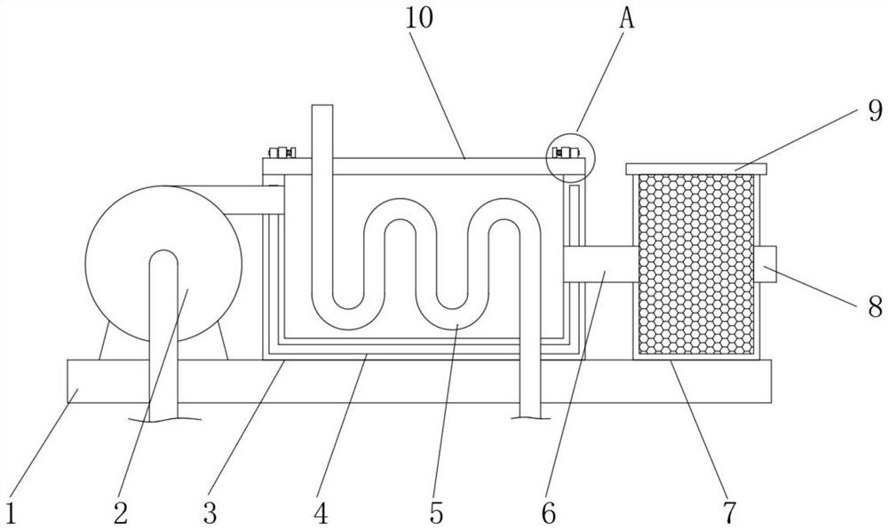
  • Ceramic tunnel kiln waste gas waste heat recoverer
  • Ceramic tunnel kiln waste gas waste heat recoverer

Examples


Embodiment Construction

[0017] The following will clearly and completely describe the technical solutions in the embodiments of the present invention with reference to the accompanying drawings in the embodiments of the present invention. Obviously, the described embodiments are only some, not all, embodiments of the present invention. Based on the embodiments of the present invention, all other embodiments obtained by persons of ordinary skill in the art without making creative efforts belong to the protection scope of the present invention.

[0018] In the description of the present invention, it should be noted that the orientations or positional relationships indicated by the terms "upper", "lower", "inner", "outer", "top / bottom" etc. are based on the orientations shown in the drawings Or positional relationship is only for the convenience of describing the present invention and simplifying the description, but does not indicate or imply that the device or element referred to must have a specific ...


PUM


Abstract

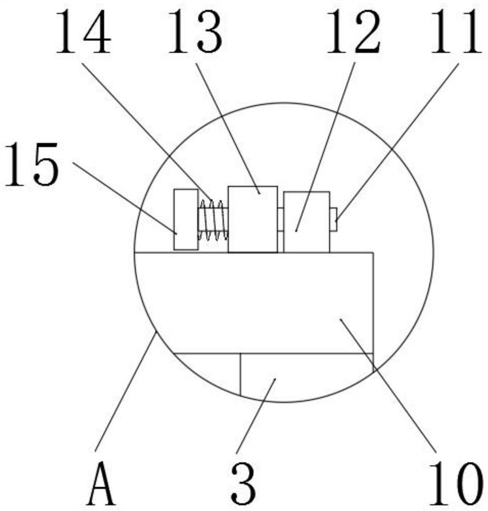
The invention discloses a ceramic tunnel kiln waste gas waste heat recoverer, and relates to tunnel kiln equipment. The ceramic tunnel kiln waste gas waste heat recoverer specifically comprises a mounting plate, wherein a recovery box is fixedly arranged in the middle of the upper surface of the mounting plate, and a sealing cover is fixedly arranged at the top of the recovery box; a preheating pipe is fixedly arranged in the recovery box, and an induced draft fan is fixedly arranged on the mounting plate on one side of the recovery box through bolts; the input end of the induced draft fan extends into the tunnel kiln, and the output end of the induced draft fan communicates with one side of the recovery box; an output end is arranged on the other side of the recovery box and fixedly connected with one end of a connecting pipe, and the other end of the connecting pipe is fixedly connected with the input end of a filter box; and an air outlet is formed in the other side of the filter box. In the implementation process of the ceramic tunnel kiln waste gas waste heat recoverer, the problem that cold air enters the tunnel kiln, so that the heat loss of the tunnel kiln is increased is avoided, and the heat utilization rate of the tunnel kiln is fully increased.

Description

technical field [0001] The invention relates to tunnel kiln equipment, in particular to a ceramic tunnel kiln waste gas waste heat recovery device. Background technique [0002] The tunnel kiln is a kiln similar to a tunnel, which is built of refractory materials, thermal insulation materials and building materials, and is equipped with kiln cars and other vehicles. It is a modern thermal equipment for continuous firing. [0003] Tunnel kilns are widely used in the roasting production of ceramic products, and are also used in metallurgical industries such as abrasives. Among them, the latest tunnel kiln designed in Leningrad, Russia is more advanced. [0004] When the existing tunnel cellar is in use, the heat loss is large, and most of the exhaust gas is directly discharged into the air, which will cause environmental pollution, reduce the heat utilization rate of the tunnel cellar, and also reduce the environmental protection of the tunnel cellar. Contents of the invent...

Claims


Application Information

Patent Timeline
IPC IPC(8): F27D17/00
CPCF27D17/004F27D17/008Y02P10/25
Inventor 胡俊明
Owner HUBEI XISHUI KEMEI MACHINERY
Learn More