Double sided ring spinning machine

A technology of ring spinning machine and spinning machine, which is applied in the direction of spinning machine, continuous winding spinning machine, textile and papermaking, etc., which can solve the problems of occupying space, reduce workload, improve heat loss, The effect of simplifying assembly

Inactive Publication Date: 2019-02-05
SAURER GERMANY GMBH & CO KG
View PDF10 Cites 0 Cited by
  • Summary
  • Abstract
  • Description
  • Claims
  • Application Information

AI Technical Summary

Problems solved by technology

Separate gearing also takes up a lot of space

Method used


Image

  • Double sided ring spinning machine
  • Double sided ring spinning machine
  • Double sided ring spinning machine

Examples


Embodiment Construction

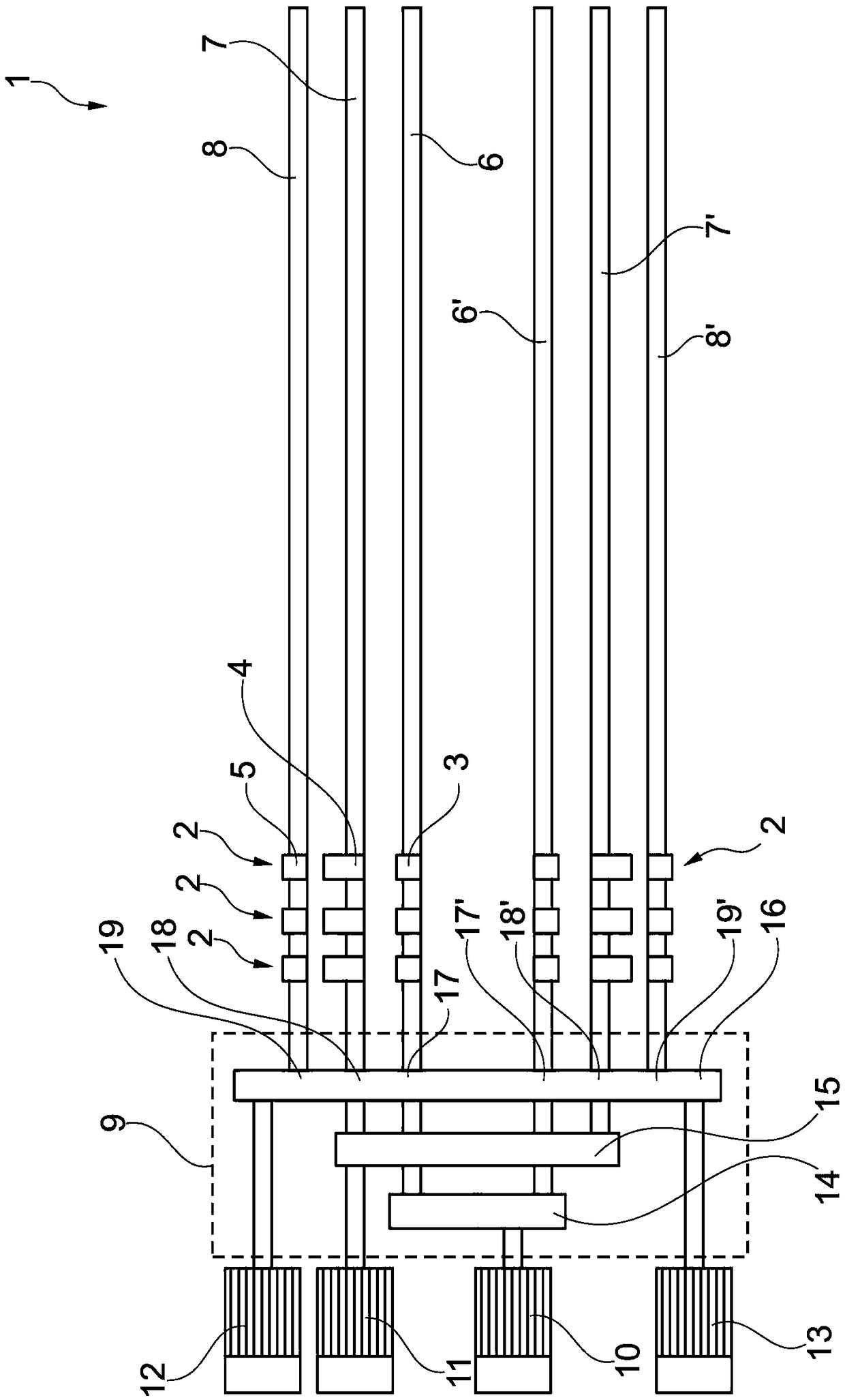
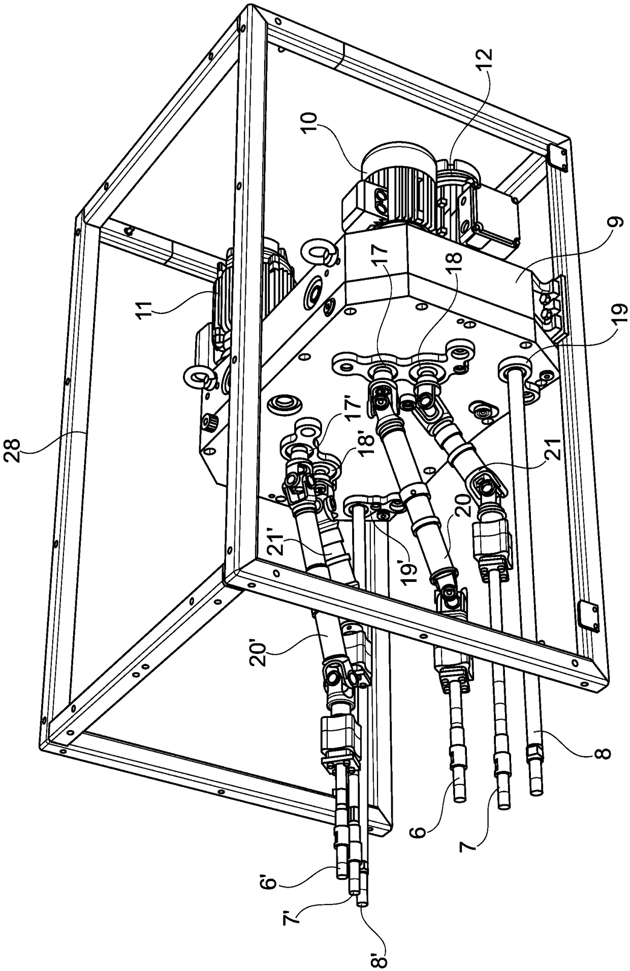
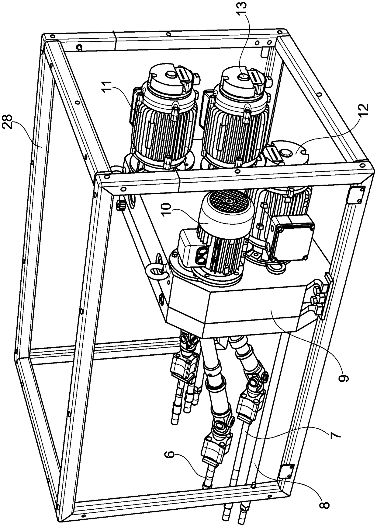
[0020] figure 1 A double-sided ring spinning machine 1 according to the invention is shown. As ring spinning machines are generally known, the drawings are limited to the necessary parts for explaining the invention. Each side of the ring spinning machine comprises a plurality of adjacently arranged drafting devices 2, only three of which are shown here. Only the feed roller 3, the lower intermediate roller 4 and the lower output roller 5 of the drafting device 2 are shown. The lower feed roller 3, the lower middle roller 4 and the lower output roller 5 on one side are arranged adjacent to each other on the shaft respectively and form the feed roller zipper 6,6', the middle roller zipper 7,7' and the output roller zipper 8,8 '. The lower feed roller 3, the lower intermediate roller 4 and the lower output roller 5 all have independent drives with independent transmissions and one or more independent motors. The lower feed roller 3 is driven by the shafts of the lower feed r...


PUM


Abstract

The present invention relates to a double-sided ring spinning machine (1) with a drafting device (2) on each side. Each of the drafting devices (2) includes a lower feeding roller (3), a lower and middle roller (4), and a lower discharging roller roller (5). A first motor (10) is allocated to the lower feeding rollers (3), a second motor (11) is allocated to the lower and middle rollers (4), and a third motor (12) is allocated to the lower discharging roller rollers (5). The first motor (10) is connected to the lower feeding rollers (3) through a first transmission device (14), the second motor (11) is connected to the lower and middle rollers (4) through a second transmission device (15), and the third motor (12) is allocated to the lower discharging roller rollers (5) through a third transmission device (16). According to the machine, the first, second and third transmission devices (14, 15, 16) are mounted in a shared transmission device shell (9).

Description

technical field [0001] The present invention relates to a double-sided ring spinning machine with a drafting device on each side. Each drafting device includes a lower feed roller, a lower intermediate roller and a lower output roller. The first motor is assigned to the lower feed roller, the second motor is assigned to the lower middle roller, and the third motor is assigned to the lower output roller. The first motor is connected to the lower feed roller through a first transmission, the second motor is connected to the lower intermediate roller through a second transmission, and the third motor is connected to the lower output roller through a third transmission. Background technique [0002] DE 10 2005 054 024 A1 discloses a ring spinning machine with a drafting device, in which the lower feed roller, the lower intermediate roller and the lower output roller are each driven by independent motors. Independent gearing is assigned to each motor. Each transmission is hous...

Claims


Application Information

Patent Timeline
Patent Type & Authority Patents(China)
IPC IPC(8): D01H5/32D01H5/22
CPCD01H5/32D01H1/22
Inventor 彼得·曼恩
Owner SAURER GERMANY GMBH & CO KG
Why Eureka
Try Eureka