
Steel friction hinge energy dissipation straining beam structure for double column piers and construction method thereof

A technology for tying beams and beams, applied in the field of steel friction hinge energy-dissipating tie-beam structures and their construction, can solve the problems of rigidity, stability impact, labor cost, beam deformation, etc. Compressive stability and lateral stiffness, easy repair, and the effect of reducing residual deformation

Active Publication Date: 2021-05-07
HEFEI UNIV OF TECH
View PDF3 Cites 2 Cited by
  • Summary
  • Abstract
  • Description
  • Claims
  • Application Information

AI Technical Summary

Problems solved by technology

[0003] At present, reinforced concrete structures are generally used in the design of tie beams for double-column piers, but under strong earthquakes, the tie beams are prone to deformation
In many earthquakes, the damage and failure of reinforced concrete tie beams is a common earthquake damage. It needs to spend manpower, material and financial resources to repair and strengthen after the earthquake, which will affect the post-earthquake traffic recovery and delay the earthquake relief work. The rigidity and stability of the double-column pier tie-beam structure are easily affected

Method used


Image

  • Steel friction hinge energy dissipation straining beam structure for double column piers and construction method thereof
  • Steel friction hinge energy dissipation straining beam structure for double column piers and construction method thereof
  • Steel friction hinge energy dissipation straining beam structure for double column piers and construction method thereof

Examples


Embodiment Construction

[0023] combined with Figure 1-5 , the specific embodiments of the present invention are described as follows:

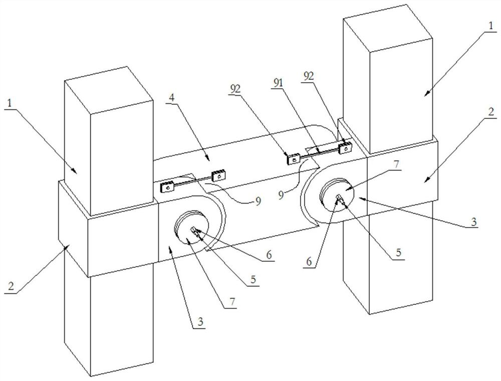
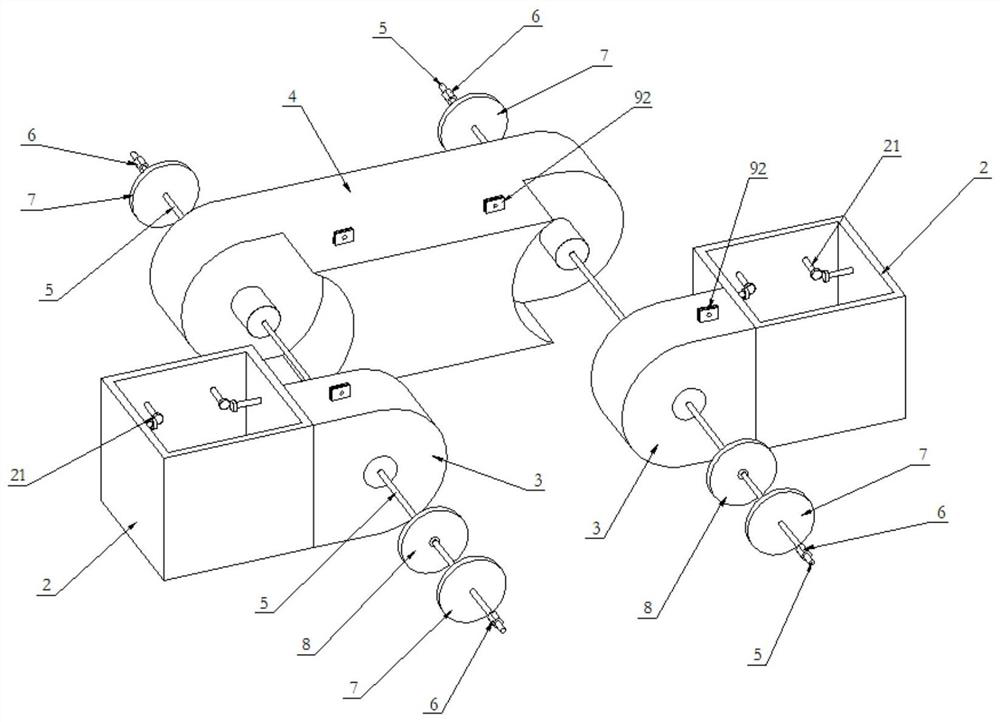
[0024] like figure 1 , 2 , 3, 4, and 5, a steel friction hinge energy-dissipating beam structure for a double-column pier, including a pier column 1, a beam 4, and both ends of the beam 4 are respectively connected by a steel sleeve 2 and an ear beam 3 On the outer walls of two vertical pier columns 1, steel sleeves 2 are sheathed on the outer walls of pier columns 1 through shear welding studs 21. The pressure applied by 5 is connected with the beam 4 to form a steel friction hinge structure.

[0025] Among them, in the entire steel friction hinge structure, the other end of the ear beam 3 is set as a semicircle, the center of the semicircle of the ear beam 3 is provided with an ear beam through hole 31, and both ends of the cross beam 4 are provided with arc-shaped concave platforms. 41. The center of the concave platform 41 is provided with a circular protrud...


PUM


Abstract

The invention discloses a steel friction hinge energy dissipation straining beam structure for double column piers. The steel friction hinge energy dissipation straining beam structure comprises a cross beam arranged between two pier stand columns, the two ends of the cross beam are connected to the outer walls of the two vertically-arranged pier stand columns through steel sleeves and lug beams correspondingly, and the outer walls of the pier stand columns are sleeved with the steel sleeves through shear-resistant welding studs; one end of the lug beam is welded outside the steel sleeve, and the other end is connected with the cross beam through pressure applied by the prestressed reinforcement to form a steel friction hinge structure. The invention further discloses a construction method of the steel friction hinge energy dissipation straining beam structure for the double column piers. According to the steel friction hinge energy dissipation straining beam structure for the double column piers and the construction method thereof, the structure is simple and practical, the transverse compression resistance stability and transverse rigidity of the double column piers can be improved, earthquake input energy is absorbed through plasticity of the straining beam, meanwhile, residual deformation of the straining beam is reduced through superelasticity of the shape memory alloy, and the straining beam with residual deformation after the earthquake is convenient to repair.

Description

technical field [0001] The invention relates to the field of anti-seismic and shock-absorbing technologies of bridge structures, in particular to a steel friction hinge energy-dissipating beam structure for double-column piers and a construction method thereof. Background technique [0002] Due to the complex topography and landforms in western China, highway and railway lines often cross deep mountains and valleys. The statistical results of bridges built or under construction in the western region show that more than 40% of the bridge piers are over 40m high. The pier height of some bridges exceeds 100m, for example, the pier height of Huatupo Bridge reaches 110m. Bridge structures in this terrain often employ double-column frame piers. In the static design of double-column piers, reinforced concrete tie beams are usually set between the two columns, so as to increase the lateral stiffness of the pier and improve its lateral stability. [0003] At present, reinforced co...

Claims


Application Information

Patent Timeline
IPC IPC(8): E01D19/02E01D21/00E04B1/98E04H9/02
CPCE01D19/02E01D21/00E04B1/98E04H9/021Y02A30/30
Inventor 刘笑显王静峰郭晨烨赵正睿丁哲邓云虎吴文静
Owner HEFEI UNIV OF TECH
Learn More