
Large-flow low-noise brushless electronic fan and automatic machining equipment thereof

An electronic fan and processing equipment technology, applied in metal processing equipment, welding equipment, mechanical equipment, etc., can solve the problems of high labor intensity, low work efficiency, low position accuracy, etc., to improve product work efficiency and reduce labor costs. Labor intensity, the effect of improving position accuracy

Inactive Publication Date: 2021-04-30
杭州松浦电器有限公司
View PDF0 Cites 1 Cited by
  • Summary
  • Abstract
  • Description
  • Claims
  • Application Information

AI Technical Summary

Problems solved by technology

[0004] This welding method requires the welder to set the welding point with his eyesight and experience. The position accuracy is not high, and the uneven distribution of the blades makes it shake during the rotation process. The welding method needs to be operated at close range. The welder needs to wear protective clothing and walk around Walking on the roulette, the work efficiency is low and the labor intensity of the workers is high. The convenience of installation and the stability of the current structure need to be improved. Therefore, we propose a large-flow, low-noise brushless electronic fan and its automatic processing equipment.

Method used


Image

  • Large-flow low-noise brushless electronic fan and automatic machining equipment thereof
  • Large-flow low-noise brushless electronic fan and automatic machining equipment thereof
  • Large-flow low-noise brushless electronic fan and automatic machining equipment thereof

Examples


Embodiment Construction

[0024] The following will clearly and completely describe the technical solutions in the embodiments of the present invention with reference to the accompanying drawings in the embodiments of the present invention. Obviously, the described embodiments are only some, not all, embodiments of the present invention. Based on the embodiments of the present invention, all other embodiments obtained by persons of ordinary skill in the art without making creative efforts belong to the protection scope of the present invention.

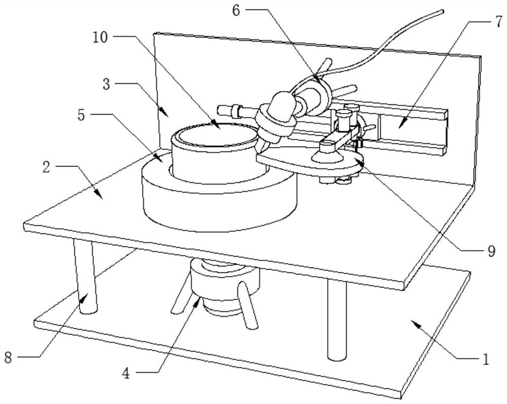
[0025] see Figure 7 , a brushless electronic fan with high flow rate and low noise, including fan blade 9, impeller 10, housing 11, air outlet 12 and switch 13, the inner wall of the housing 11 is fixed with a brushless motor, and the brushless motor outputs The impeller 10 is installed on the end rotation, the outer wall of the impeller 10 is equidistantly equipped with fan blades 9, the upper surface of the housing 11 is fixedly installed on the outer wall ...


PUM


Abstract

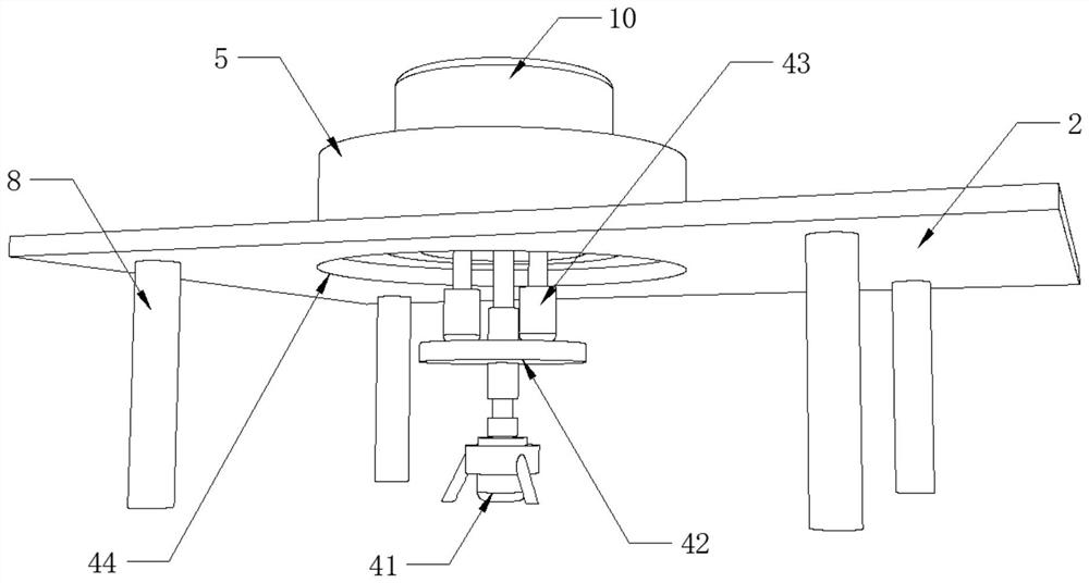
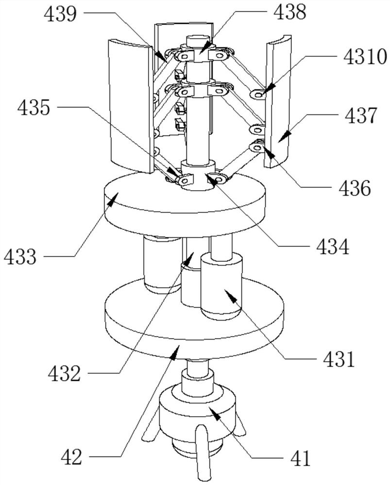
The invention discloses a large-flow low-noise brushless electronic fan and automatic machining equipment thereof. The large-flow low-noise brushless electronic fan comprises a base plate, a mounting plate, a side plate, a positioning body, a supporting column, fan blades and an impeller, wherein the supporting column is fixedly mounted on the upper surface of the base plate, the mounting plate is fixedly mounted on the upper surface of the supporting column, the side plate is fixedly mounted on one side of the upper surface of the mounting plate, the impeller is movably arranged on the upper surface of the mounting plate, the positioning body is fixedly mounted on the inner wall of the mounting plate, the positioning body is movably connected with the impeller in an inserted mode, the fan blades are movably arranged on the upper surface of the mounting plate, and a limiting device for movably clamping the impeller in a retractable mode is arranged at the position, corresponding to the impeller, of the upper surface of the base plate. According to the large-flow low-noise brushless electronic fan and the automatic machining equipment thereof, the position accuracy during welding of the fan blades and the impeller is improved, automatic welding of the fan blades and the impeller is achieved, the labor intensity of workers is reduced, the working efficiency of products is improved, and the large-flow low-noise brushless electronic fan is convenient to use by a user.

Description

technical field [0001] The invention relates to the technical field of fan processing, in particular to a brushless electronic fan with large flow rate and low noise and automatic processing equipment thereof. Background technique [0002] The brushless DC motor consists of a motor body and a driver, and is a typical mechatronic product. Since the brushless DC motor operates in a self-controlled manner, it does not add an additional starting winding to the rotor like a synchronous motor with heavy load under variable frequency speed regulation, nor does it cause oscillation and out of step when the load changes suddenly. The permanent magnets of brushless DC motors with small and medium capacity are now mostly made of rare earth NdFeB materials with high magnetic energy levels. Therefore, the volume of the rare earth permanent magnet brushless motor is reduced by one frame size compared with the three-phase asynchronous motor with the same capacity. [0003] The brushless ...

Claims


Application Information

Patent Timeline
Patent Type & Authority Applications(China)
IPC IPC(8): F04D25/08F04D29/52F04D29/32F04D29/34F04D29/38F04D29/64F04D27/00B23K37/00B23K37/04B23K37/053B23K37/02
CPCB23K37/00B23K37/0247B23K37/0443B23K37/053F04D25/08F04D27/00F04D29/325F04D29/34F04D29/388F04D29/522F04D29/646
Inventor 梁伟
Owner 杭州松浦电器有限公司
Learn More