
Fixing and clamping tool for mechanical raw material cutting

A technology for fixing clamping and raw materials, applied in positioning devices, metal processing machinery parts, clamping and other directions, can solve the problems of increasing rework rate and scrap rate, cutting error of mechanical raw materials, unfavorable production efficiency, etc., to reduce workload, The effect of improving production efficiency and reducing error factors

Active Publication Date: 2021-04-30
吉林省弘宇电力设备有限公司
View PDF16 Cites 0 Cited by
  • Summary
  • Abstract
  • Description
  • Claims
  • Application Information

AI Technical Summary

Problems solved by technology

[0006] The purpose of the present invention is to provide a fixed clamping tool for cutting mechanical raw materials, to solve the problem that the existing fixed and clamping tooling for mechanical raw materials proposed in the above background technology mostly simply fixes the mechanical raw materials through a pressing plate, and in the process of cutting Among them, especially cylindrical mechanical materials are prone to rotational displacement, so it is very easy to cause errors in the cutting of mechanical raw materials, which increases the rework rate and scrap rate, which is not conducive to the improvement of production efficiency, and in the process of cutting mechanical raw materials. Waste will also affect the production accuracy of the product and increase the workload of the staff

Method used


Image

  • Fixing and clamping tool for mechanical raw material cutting
  • Fixing and clamping tool for mechanical raw material cutting
  • Fixing and clamping tool for mechanical raw material cutting

Examples


Embodiment Construction

[0026] The following will clearly and completely describe the technical solutions in the embodiments of the present invention with reference to the accompanying drawings in the embodiments of the present invention. Obviously, the described embodiments are only some, not all, embodiments of the present invention.

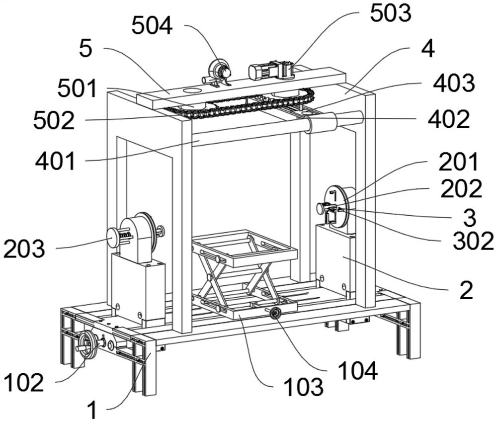
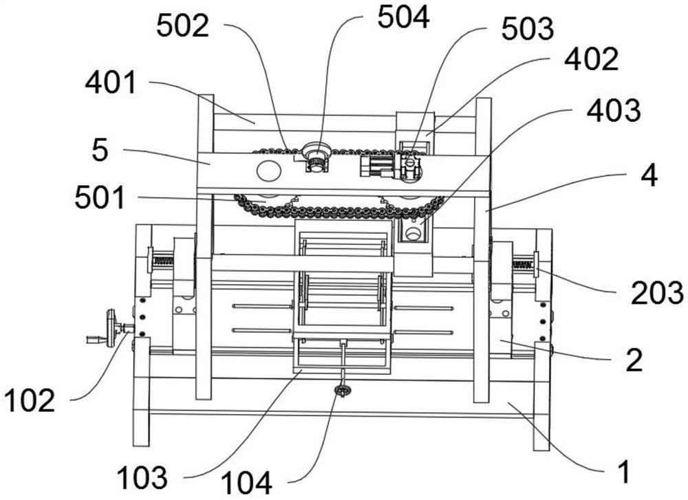
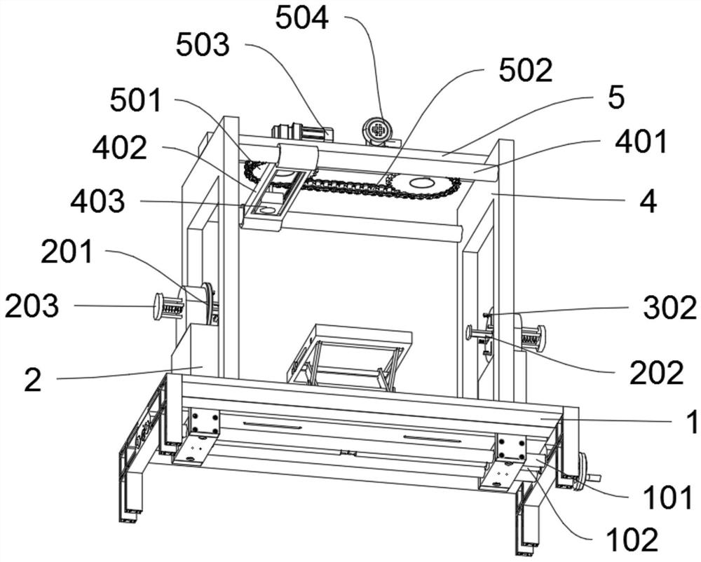
[0027] see Figures 1 to 6 Figure, an embodiment provided by the present invention: a fixed clamping tool for cutting mechanical raw materials, including a base 1; the base 1 also includes a first slide bar 101; the bottom of the base 1 is fixed with a first slide bar by bolts 101; the top of the first slider 101 is slidably provided with a sliding block 2, and the bottom of the sliding block 2 is provided with a screw hole; the sliding block 2 also includes a fixed plate 201; the front side of the sliding block 2 is fixed with a fixed plate by bolts 201, and the middle of the inner side of the fixed disk 201 is provided with a slot hole; the inner side of the fixed ...


PUM


Abstract

The invention discloses a fixing and clamping tool for mechanical raw material cutting, and relates to the technical field of machining. The fixing and clamping tool for mechanical raw material cutting solves the problems that errors are likely to occur in the mechanical raw material cutting process, which goes against the improvement of the production efficiency, a large number of waste chips re generated in the cutting process, and the workload of workers is increased. The fixing and clamping tool for mechanical raw material cutting comprises a base. Sliding blocks are arranged at the top of a first sliding rod in a sliding manner. Sliding seats are fixedly arranged on the inner side of each fixing disc in an annular array shape. A mounting frame is fixedly arranged at the top of the base through bolts. A fixing plate is fixedly arranged at the top of the mounting frame through bolts. By arranging the base, the sliding blocks and the sliding seats, the stability of raw materials in the cutting process and the accuracy of finished products can be further enhanced, and the production efficiency is improved; and through the arrangement of the mounting frame and the fixing plate, the top of the base can be cleaned in the cutting process, and the workload of workers is lightened.

Description

technical field [0001] The invention relates to the technical field of mechanical processing, in particular to a fixed clamping tool for cutting mechanical raw materials. Background technique [0002] In the process of mechanical processing, it is often necessary to cut iron blocks or iron bars. Since the mechanical raw materials will be displaced by external forces during the cutting process, this requires a fixed clip used in the cutting process of mechanical raw materials. Hold tooling. [0003] After retrieval, for example, the patent No. CN108723833A discloses a fixed tooling, which includes two clamping parts and several fixing devices. The two clamping parts are symmetrical to each other. The clamping part includes a base and a clamping block. There are square connecting blocks on both sides of the connecting block. There is a through hole in the middle of the connecting block. The clamping block is above the base. The length of the clamping block is the same as that...

Claims


Application Information

Patent Timeline
Patent Type & Authority Applications(China)
IPC IPC(8): B23Q3/06B23Q11/00
CPCB23Q3/062B23Q3/064B23Q11/005
Inventor 杨少波
Owner 吉林省弘宇电力设备有限公司
Learn More