Orthopaedic traction device with included angle adjustable and self-locking functions
A traction device and reconciliation technology, applied in the field of auxiliary medical devices, can solve the problems of burden on medical staff, difficult to carry and use, large traction frame frame, etc., and achieve the effect of convenient adjustment of position and angle, easy portability and cleaning
- Summary
- Abstract
- Description
- Claims
- Application Information
AI Technical Summary
Problems solved by technology
Method used
Image
Examples
Embodiment 1
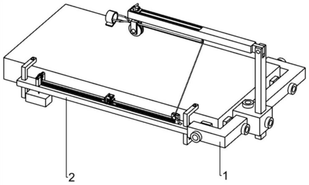
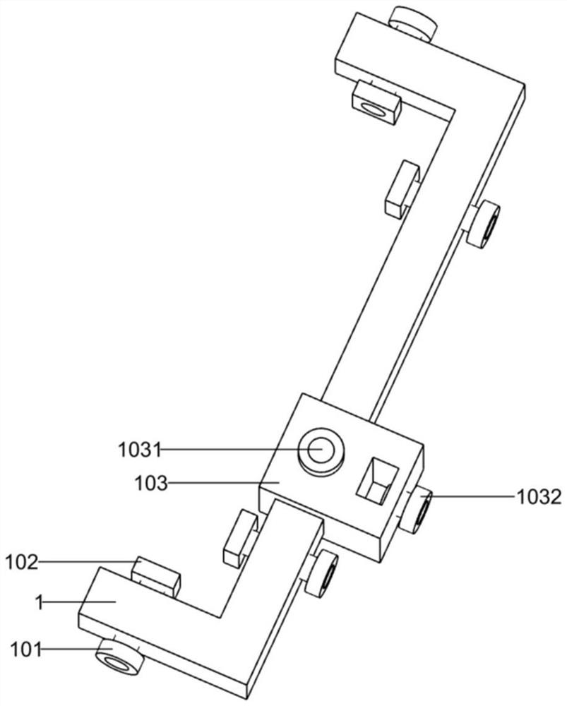
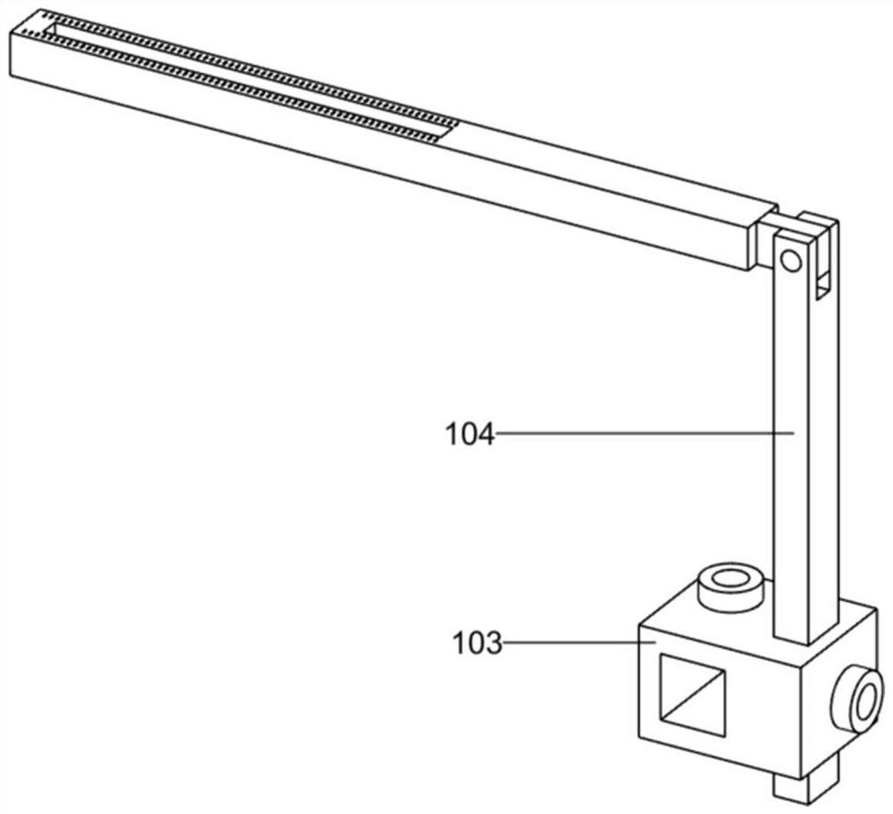
[0043]Such asFigure 1-3 Shown
[0044]The bracket portion of the present invention includes a bed fastener (1), a fixed frame fastening nail (101), a pre-tension block (102), a moving connection block (103), the connection block fastening nail (1031), the suspensory fastening nail (1032) and the right angle suspensory beam (104), the bed fastener (1) presents a C shape around the bed along one side, the fixing frame fastening nail (101) at least three, the fixing frame fastening nail (101) The thread is connected to both sides of the bed fastener (1), and the tightening block (102) is connected to the end thread of the fixed frame fastening nail (101), the moving connection block (103) The sliding connection is slid on the bed fastener (1), the connection block fastening nail (1031) is threaded to the upper side of the moving connection block (103), and there is a section on the upper side of the right angle suspensory (104). Cross slots, the right angularly hanging beam (104) is provi...
Embodiment 2
[0047]Such asFigure 4-7 Shown
[0048]The traction position control unit of the present invention includes a hanging ring (105), a T-type block (106), a crush (1061), a cylindrical (1062), a movable plate (107), a live plate guide column (1071), a live plate The spring (10711), the living plate handle (1072), the pulley frame (108), the rotating pulley (1081), the traction rope (109) and a skin tape (1091), the hanging ring (105) fixedly connected to the right angle suspension (104) Next, the T-type block (106) opens the guiding hole, the T type block (106) fixed to the cross block (1061), the cross block (1061) sliding in the In the cross slide, the cylindrical (1062) is fixed to the cross chute, and the cylindrical (1062) is secured to the cross block (107), and the movable plate (107) has a right angle suspension (104). The groove of the bump particles, the movable plate (107) slides to be attached to the T-block (106), and the living plate guide column (1071) is fixed to the upper ...
Embodiment 3
[0051]Such asFigure 8-22Shown
[0052]Further, the traction adjustment portion includes a tuning fixing frame (2), a C-shaped frame (201), a small fastening nail (2011), a tuning rotating frame (202), a tuning activity box (203), activity box Handle (2031), with tooth shaft (2032), gear (204), active rack (2041), active elliptical frame (20411), passive rack (2042), passive elliptical frame (20421), active rod (205) , Curved topping block (2051), top tightening block handle (2052), topping movable block (206), runner (2061), mobile frame (207), winding rope frame (208), rope shaft guide column ( 2081), guide post spring (2082), wired shaft (209), wound rope handle (2091) and a weighting member (210), the tension fixture (2) fixedly connected to the bed fixture (1 On the left side, there is a passage in the middle of the tuning fixing frame (2), the C-shaped frame (201), and the C-shaped frame (201) slides to the tension fixture ( 2) In the hole in both ends, the small fastening nail (2...
PUM
 Abstract
Description
Claims
Application Information
 - Generate Ideas
- Intellectual Property
- Life Sciences
- Materials
- Tech Scout
- Unparalleled Data Quality
- Higher Quality Content
- 60% Fewer Hallucinations
Browse by: Latest US Patents, China's latest patents, Technical Efficacy Thesaurus, Application Domain, Technology Topic, Popular Technical Reports.
© 2025 PatSnap. All rights reserved.Legal|Privacy policy|Modern Slavery Act Transparency Statement|Sitemap|About US| Contact US: help@patsnap.com


